
Screw for a solid-bowl centrifuge and a method of extracting oil using the centrifuge

a technology of screw-type centrifuges and screw-type centrifuges, which is applied in the direction of screw-type centrifuges, centrifuges, and centrifugal force sediment separation, etc., can solve the problems of insufficient simple provision of recesses, insufficient economic efficiency, and insufficient, so as to improve the economic efficiency of oil extraction, reduce the residual oil content, and improve the economic efficiency of the method

Inactive Publication Date: 2005-06-21
WESTFALIA SEPARATOR AG
View PDF18 Cites 5 Cited by
  • Summary
  • Abstract
  • Description
  • Claims
  • Application Information

AI Technical Summary

Benefits of technology

"The present invention provides a screw for a solid-bowl screw-type centrifuge and a method for extracting oil from fruits or seeds. The screw has at least one screw blade with recesses and blade segments in the delivery path between the screw spirals. The recesses and blade segments are constructed in a way that allows for a better separation of oil and water, resulting in a higher economic efficiency of the oil extraction process. The screw can be retrofitted into existing centrifuges and is particularly suitable for extracting oil from fruits and seeds. The combination of recesses and blade segments is important for achieving a significant increase in efficiency. The method using the screw results in a better draining of water and oil from mashes of organic materials."

Problems solved by technology

However, according to the present invention, the simple providing of such recesses is not sufficient to obtain a significant increase in efficiency.
Those blade segments extend into the conical section, which is not favorable.
In addition, those blade segments are distributed on the circumference of the screw body over its entire area, which was also found to be not favorable.
Also, by use of this prior art screw, no satisfactory economic efficiency can be achieved when extracting olive oil.

Method used


Image

  • Screw for a solid-bowl centrifuge and a method of extracting oil using the centrifuge
  • Screw for a solid-bowl centrifuge and a method of extracting oil using the centrifuge
  • Screw for a solid-bowl centrifuge and a method of extracting oil using the centrifuge

Examples


Embodiment Construction

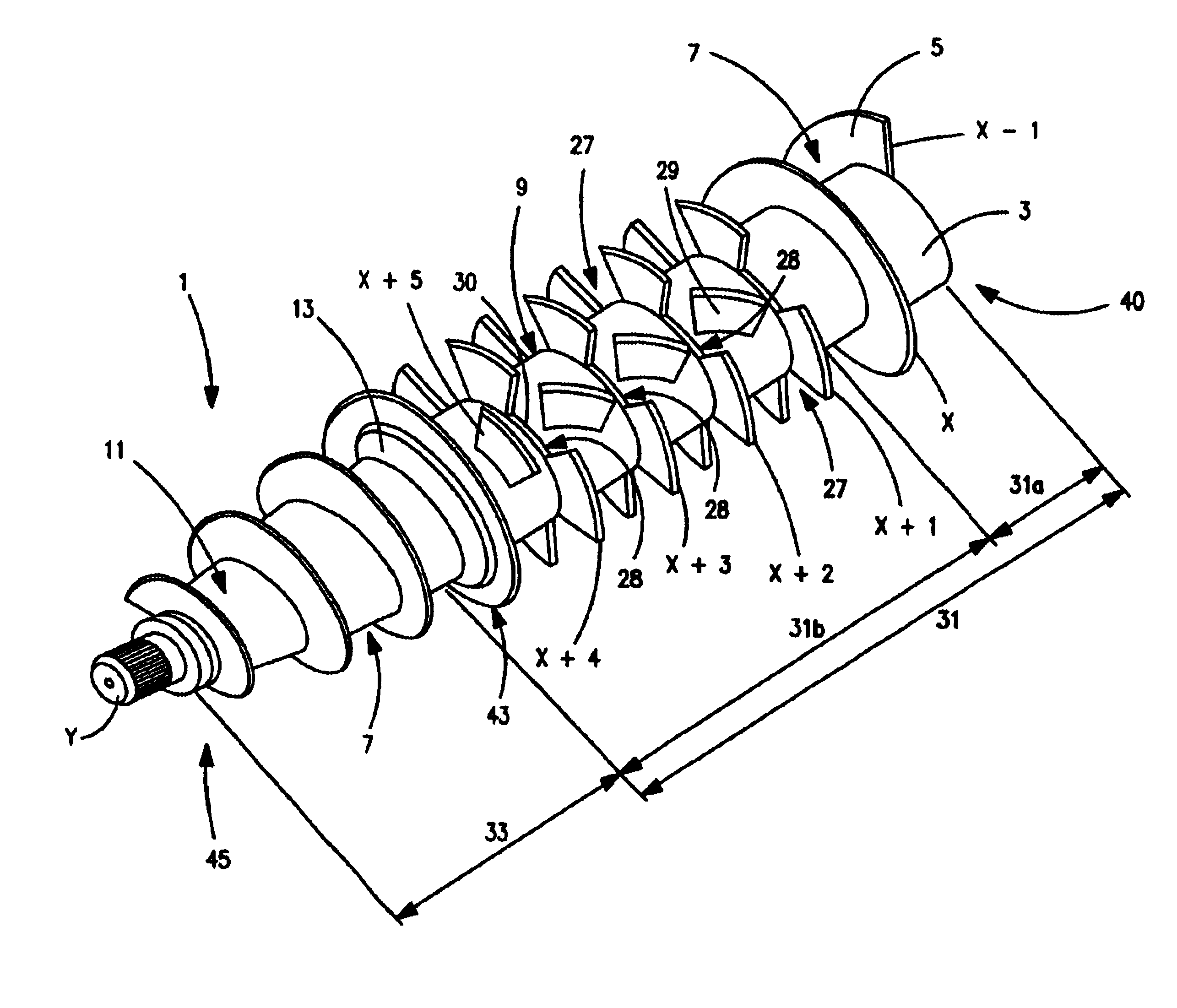
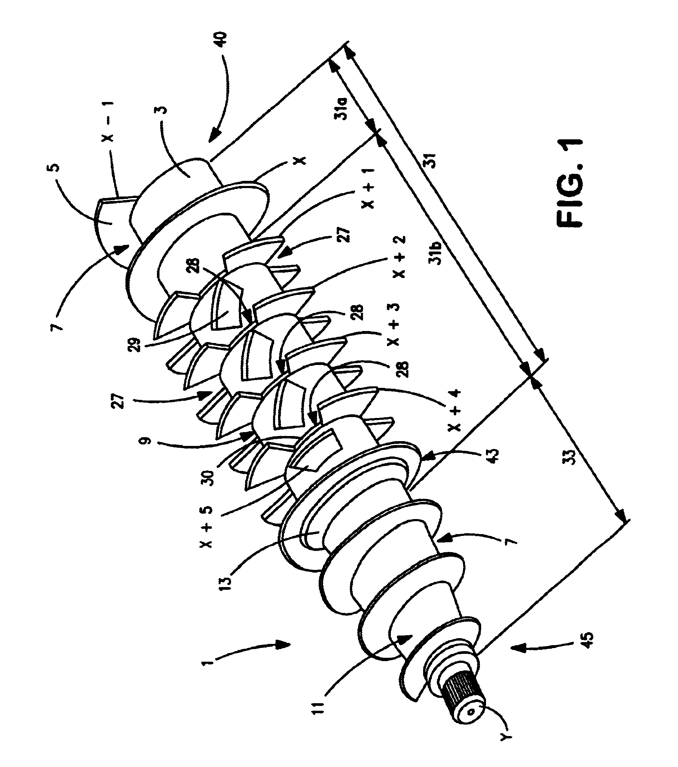
[0044]FIG. 1 illustrates a screw 1 for a solid-bowl screw-type centrifuge 50 (see FIG. 3), the screw 1 having a screw body 3 as well as, in this case, a screw blade 5 which surrounds the screw body 3 several times and forms several screw spirals (for example x, x+1, x+2, etc.).

[0045]A delivery path 7 for delivering / conveying a material to be centrifuged is formed between the screw spirals x, x+1, . . . .

[0046]In a rearward area 40 the screw body 3 has a cylindrical section 9 and, in an adjoining forward area 45, the screw body 3 has a dry zone 33 or conically tapering section 11 that is essentially conical, uniformly or non-uniformly.

[0047]In a transition area 43 between the cylindrical section 9 and the conical section 11, a retarder or disk 13 is placed on the screw body 3. This placement was found to be successful particularly in a two-phase separation process separating material into an oil phase and a water / solids phase. Such placement may not be required in a three-phase separ...


PUM

PropertyMeasurementUnit
anglesaaaaaaaaaa
distanceaaaaaaaaaa
magnitude of angleaaaaaaaaaa

Abstract

A screw for a solid-bowl screw-type centrifuge, comprising: a screw body having a circumference, a cylindrical section and a conical section; at least one screw blade surrounding the screw body several times and forming several screw spirals; a delivery path for conveying material to be centrifuged formed between the screw spirals; blade segments arranged in the delivery path between adjacent screw spirals only in a portion of the cylindrical section; and recesses in the at least one screw blade, the recesses constructed only in a portion of the cylindrical section and constructed such that the material to be centrifuged can flow through between adjacent screw spirals. A method for extracting oil in a two- and three-phase separation process using the screw of the present invention.

Description

BACKGROUND AND SUMMARY OF THE INVENTION[0001]The invention relates to a screw for a solid-bowl screw-type centrifuge and to a method of extracting oil by means of a solid-bowl screw-type centrifuge.[0002]A method which has been particularly effective for the extraction of olive oil is known from European Patent Document EP 0 557 758. In this process, a two-phase separation is carried out in which the oil is separated directly from the solids / water mixture.[0003]The efficiency of this known method is very good per se.[0004]Nevertheless, it is desirable to lower the residual oil content in a rape in order to increase the economic efficiency of the oil extraction.[0005]The present invention provides for, on the one hand, a screw for a solid-bowl screw-type centrifuge and a process for extracting oil from fruit or seed.[0006]The present invention provides for a screw or kneading screw for a solid-bowl screw-type centrifuge which has at least one screw blade and at least one screw blade ...

Claims


Application Information

Patent Timeline
Patent Type & Authority Patents(United States)
IPC IPC(8): B04B1/20B04B1/00
CPCB04B1/20Y10S494/901B04B2001/205
Inventor HRUSCHKA, STEFFENHULSMANN, ROGER
Owner WESTFALIA SEPARATOR AG
Learn More