
Receiving circuit, ultrasonic probe, and ultrasonic image displaying apparatus

Inactive Publication Date: 2012-08-02
GENERAL ELECTRIC CO
View PDF6 Cites 14 Cited by
  • Summary
  • Abstract
  • Description
  • Claims
  • Application Information

AI Technical Summary

Benefits of technology

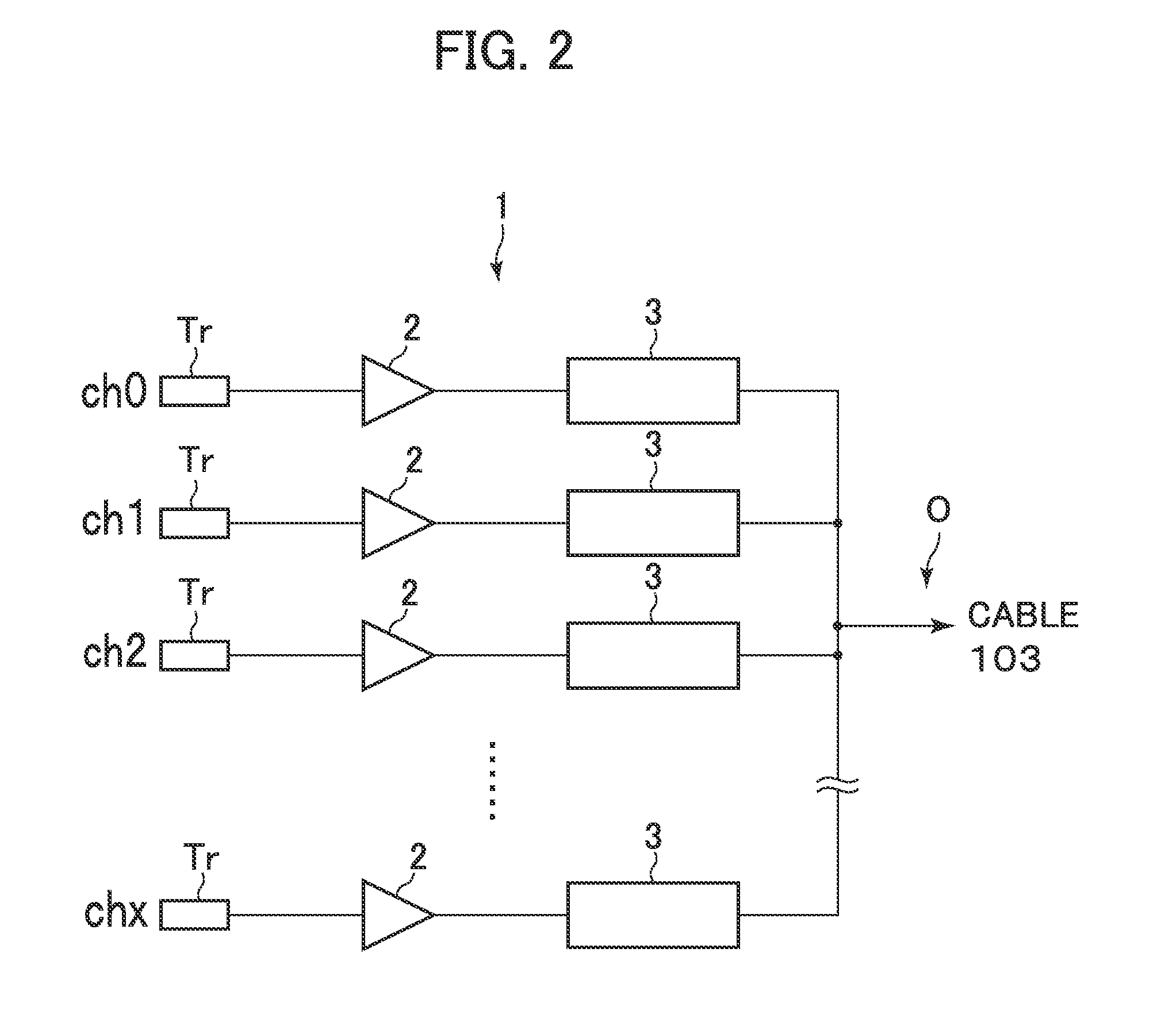
[0029]According to the above aspects of the invention, each amplification unit of the receiving circuit includes a current output amplifier. Without an adder, therefore, currents outputted from the amplification units in the individual channels are added at an output line in the stage subsequent to the amplification units. This obviates necessity for an adder. The frequency characteristic of each the current output amplifier is such that the gain is reduced as the frequency is increased toward the center frequency of ultrasonic waves. This obviates necessity for a low-pass filter or even a simple low-pass filter is sufficient. Since each the amplification unit outputs current, it is unnecessary to provide a buffer amplifier on the subsequent stage side. Because of the foregoing, it is possible to reduce the size of a receiving circuit and suppress the production of heat more than conventional. As a result, the receiving circuit can be provided in an ultrasonic probe.

Problems solved by technology

When a voltage amplifier is used, however, a buffer amplifier is required in the stage subsequent to the voltage amplifier and heat due to energy loss according thereto is produced.
As mentioned above, however, downsizing of conventional receiving circuits is limited and it is difficult to provide them in an ultrasonic probe without change.
In ultrasonic probes that are gripped by an operator, the production of heat poses a problem as compared with cases where a receiving circuit is provided in the main unit of an apparatus.

Method used


Image

  • Receiving circuit, ultrasonic probe, and ultrasonic image displaying apparatus
  • Receiving circuit, ultrasonic probe, and ultrasonic image displaying apparatus
  • Receiving circuit, ultrasonic probe, and ultrasonic image displaying apparatus

Examples


first embodiment

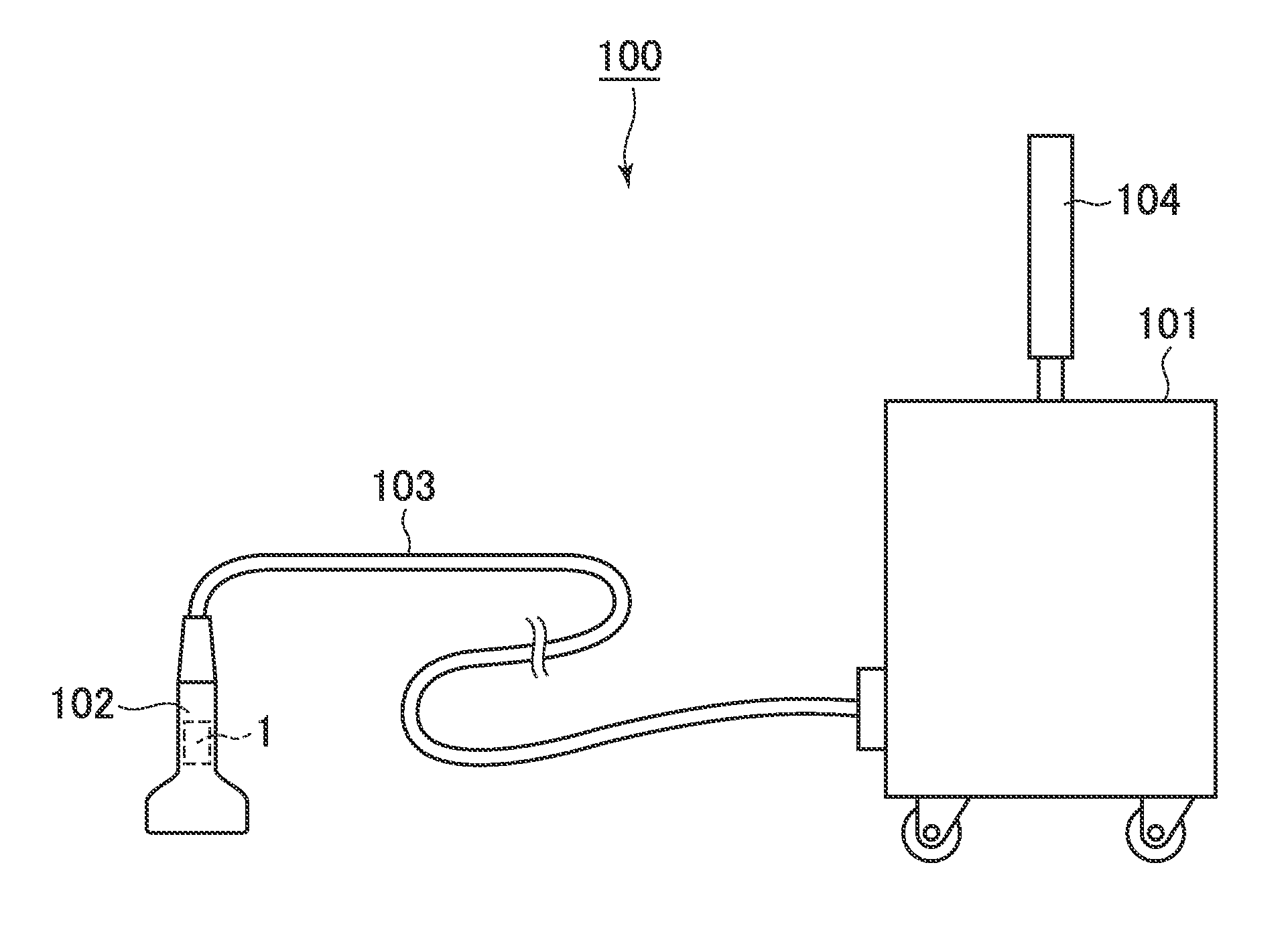
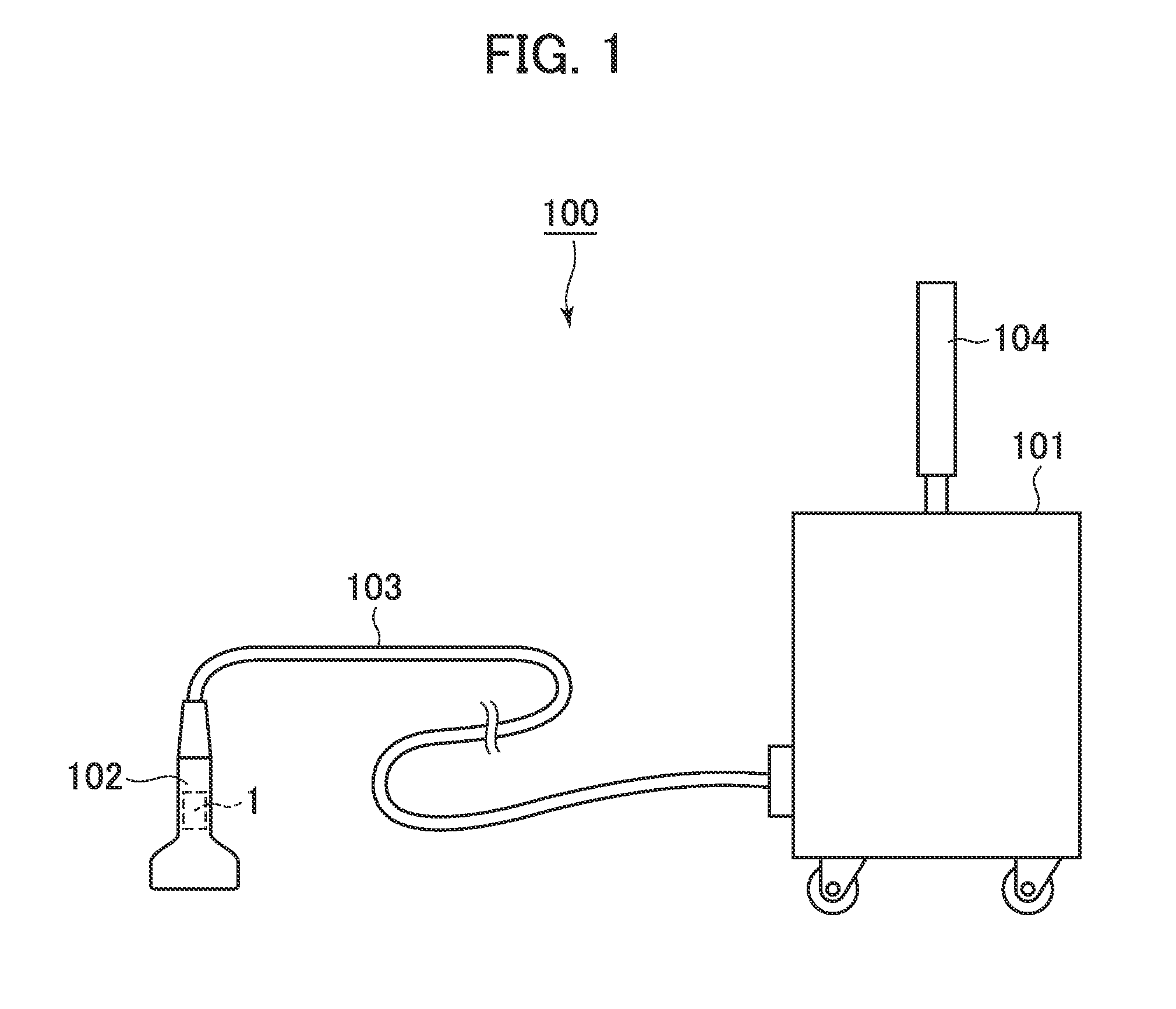
[0050]Description will be given to a first embodiment with reference to FIGS. 1-7. As illustrated in FIG. 1, an ultrasonic image displaying apparatus 100 includes an apparatus main unit 101 and an ultrasonic probe 102 connected with the apparatus main unit 101. The ultrasonic probe 102 is connected with the apparatus main unit 101 through a cable 103.

[0051]The ultrasonic probe 102 is provided with a receiving circuit 1 to which ultrasonic echo signals received at ultrasonic transducers are inputted. The ultrasonic probe 102 may be provided with a transmitting circuit though not especially shown in the diagram. The transmitting circuit drives the ultrasonic transducers of the ultrasonic probe 102 under a predetermined transmission condition and scans a scan surface with an ultrasonic beam in a sound-ray sequential manner.

[0052]The apparatus main unit 101 has output signals from the receiving circuit 1 inputted thereto through the cable 103 and the signals are A-D converted at an A-D ...

second embodiment

[0079]Description will be given to a second embodiment. The same elements as in the first embodiment will be marked with the same reference numerals or codes and the description thereof will be omitted.

[0080]In the first embodiment, the delay unit 3 is provided for the ultrasonic transducer Tr and the amplification unit 2 in each channel. In the second embodiment, meanwhile, the delay unit 3 is provided in common to the ultrasonic transducers Tr and amplification units 2 in multiple channels. In this example, as illustrated in FIG. 16, one delay unit 3 is provided in common to the ultrasonic transducers Tr and the amplification units 2 in multiple channels. An echo signal received at the ultrasonic transducer Tr in each channel is amplified at the corresponding amplification unit 2 and is inputted as a current to the delay unit 3 without exception.

[0081]Description will be given to the configuration of the delay unit 3 in this example with reference to FIG. 17. It will be assumed th...

third embodiment

[0084]Description will be given to a third embodiment. The same elements as in the above embodiments will be marked with the same reference numerals and code and the description thereof will be omitted.

[0085]Also in the third embodiment, the delay unit 3 is provided in common to ultrasonic transducers Tr and amplification units 2 in multiple channels as in the second embodiment. Unlike the second embodiment, however, multiple delay units are provided in common to ultrasonic transducers Tr and amplification units 2 in some channels of all the channels. As a result, signals in some channels of a larger group of channels are inputted to each delay unit 3. In this example, one delay unit 3 is provided for ultrasonic transducers Tr and amplification units 2 equivalent to three channels as illustrated in FIG. 18. As illustrated in FIG. 19, therefore, each delay unit 3 is provided with write switches SWw1, SWw2, SWw3, . . . , SWwn of the write circuits 31-1, 31-2, 31-3, . . . , 31-n on a t...


PUM


Abstract

A receiving circuit in an ultrasonic probe that includes an ultrasonic transducer configured to receive ultrasonic waves is provided. The receiving unit includes an amplification unit configured to amplify an echo signal received at the ultrasonic transducer. The amplification unit includes a current output amplifier. The receiving circuit further includes a delay unit configured to provide a delay time to output signals of the amplification unit.

Description

BACKGROUND OF THE INVENTION[0001]1. Field of the Invention[0002]The present invention relates to a receiving circuit including an amplification unit that amplifies ultrasonic echo signals and a delay unit that provides output signals of the amplification unit with a predetermined delay time and an ultrasonic probe and an ultrasonic image displaying apparatus equipped with this receiving circuit.[0003]2. Description of Related Art[0004]In ultrasonic image displaying apparatuses, an ultrasonic wave is transmitted from multiple ultrasonic transducers provided in an ultrasonic probe and an echo signal is received at each ultrasonic transducer. An echo signal received at each ultrasonic transducer is inputted to a receiving circuit and phased and added there. As a result, one reception beam is formed.[0005]At the receiving circuit, an echo signal is amplified at an amplification unit provided in each ultrasonic transducer. To output signals of each amplification unit, a predetermined del...

Claims


Application Information

Patent Timeline
IPC IPC(8): A61B8/14
CPCG01S7/52025G10K11/346G01S15/8915G01S7/5208A61B8/14G01N29/24
Inventor AMEMIYA, SHINICHIHAIDER, BRUNORAO, NARESH KESAVAN
Owner GENERAL ELECTRIC CO
Learn More