
Transceiver coil for auditory prosthesis

a transceiver coil and auditory prosthesis technology, applied in the field of transceiver coils for auditory prosthesis, can solve the problem of not being able to derive suitable benefits from conventional hearing aid systems, and achieve the effects of reducing materials and weight, improving construction efficiency, and simplifying the shape of the casing

Inactive Publication Date: 2007-08-21
COCHLEAR LIMITED
View PDF13 Cites 20 Cited by
  • Summary
  • Abstract
  • Description
  • Claims
  • Application Information

AI Technical Summary

Benefits of technology

[0021]It has been realised that in order to increase efficiency of transmission, it is desirable to tune a transmission coil by use of a relatively large inductance and a relatively small capacitance. However, when a small capacitance is used to tune the coil, the presence of stray capacitance such as the skin-to-coil capacitance, can have a considerable impact on tuning frequency. It has further been realised that a skin-to-coil capacitance can vary considerably from one user to the next, for example due to differing skin thickness proximal to the coil, making it difficult to compensate for such capacitance when designing a coil. By providing a shield for reducing a skin-to-coil capacitance, the present invention improves the stability of a tuned frequency of the coil when brought close to a user's skin.
[0045]Embodiments of the fifth aspect of the invention may be advantageous in that only a single “spoken” is provided in supporting the magnetic means, thus reducing materials and weight required in forming the antenna casing as compared to the required materials and weight of a “hub and spokeantenna design. Further, the fifth aspect of the present invention may be advantageous in facilitating automated production of antennae in which the at least one turn of the antenna is formed on a PCB. In particular, having a single spoke simplifies the shape of a casing and increases the ease of construction of a 2-part “snap-fit” mould into which such a PCB is to be placed, as a reduced number of spokes are present requiring the snap fit. The fifth aspect of the invention may also provide a stylised attractive antenna, which can be an important consideration where the antenna is to be worn by a user in a prominent body position, such as on the head behind the ear.

Problems solved by technology

These people are thus unable to derive suitable benefit from conventional hearing aid systems, no matter how loud the acoustic stimulus is made, because there is damage to or absence of the mechanism for nerve impulses to be generated from sound in the normal manner.

Method used


Image

  • Transceiver coil for auditory prosthesis
  • Transceiver coil for auditory prosthesis
  • Transceiver coil for auditory prosthesis

Examples


Embodiment Construction

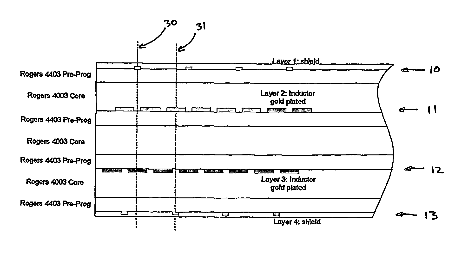
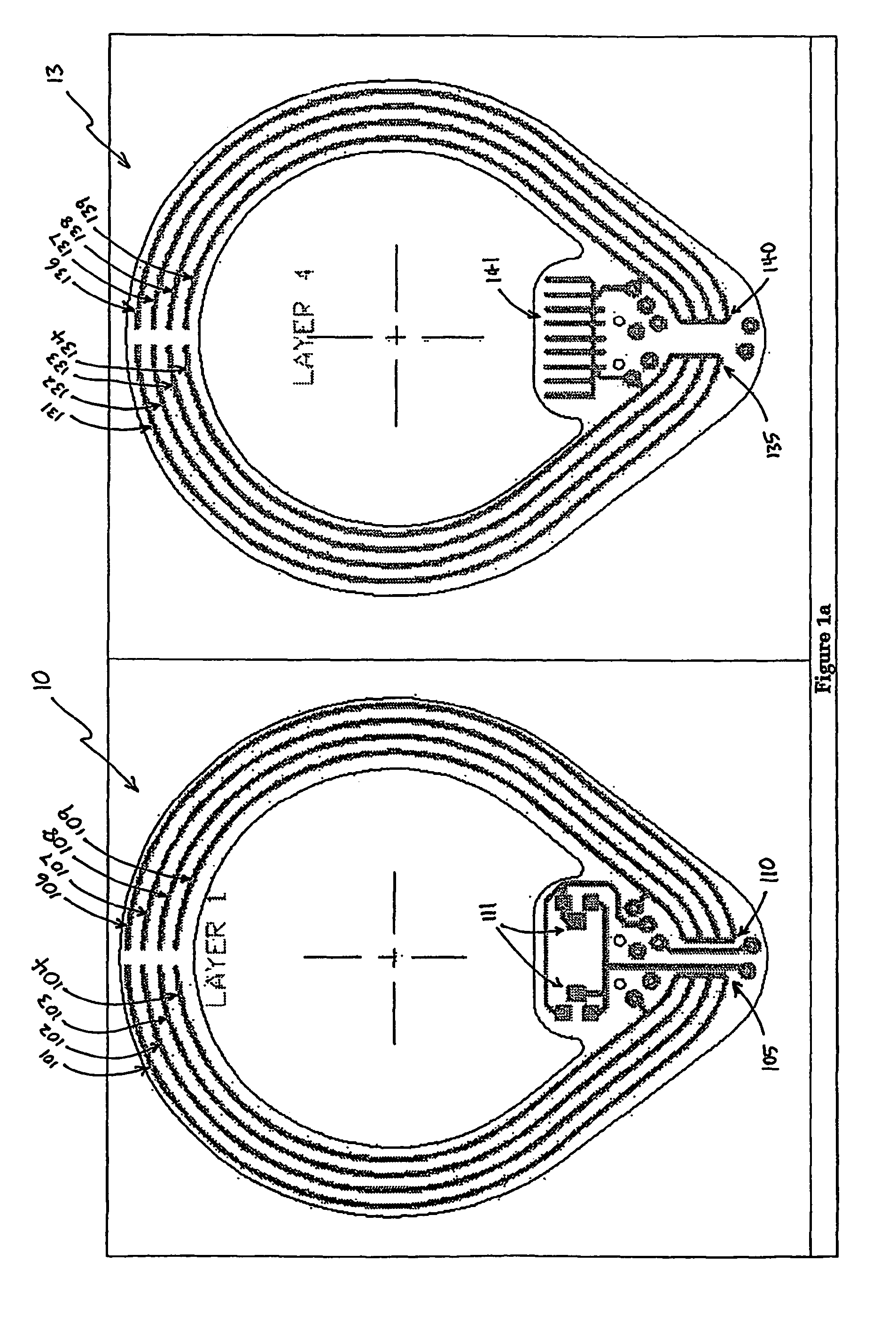
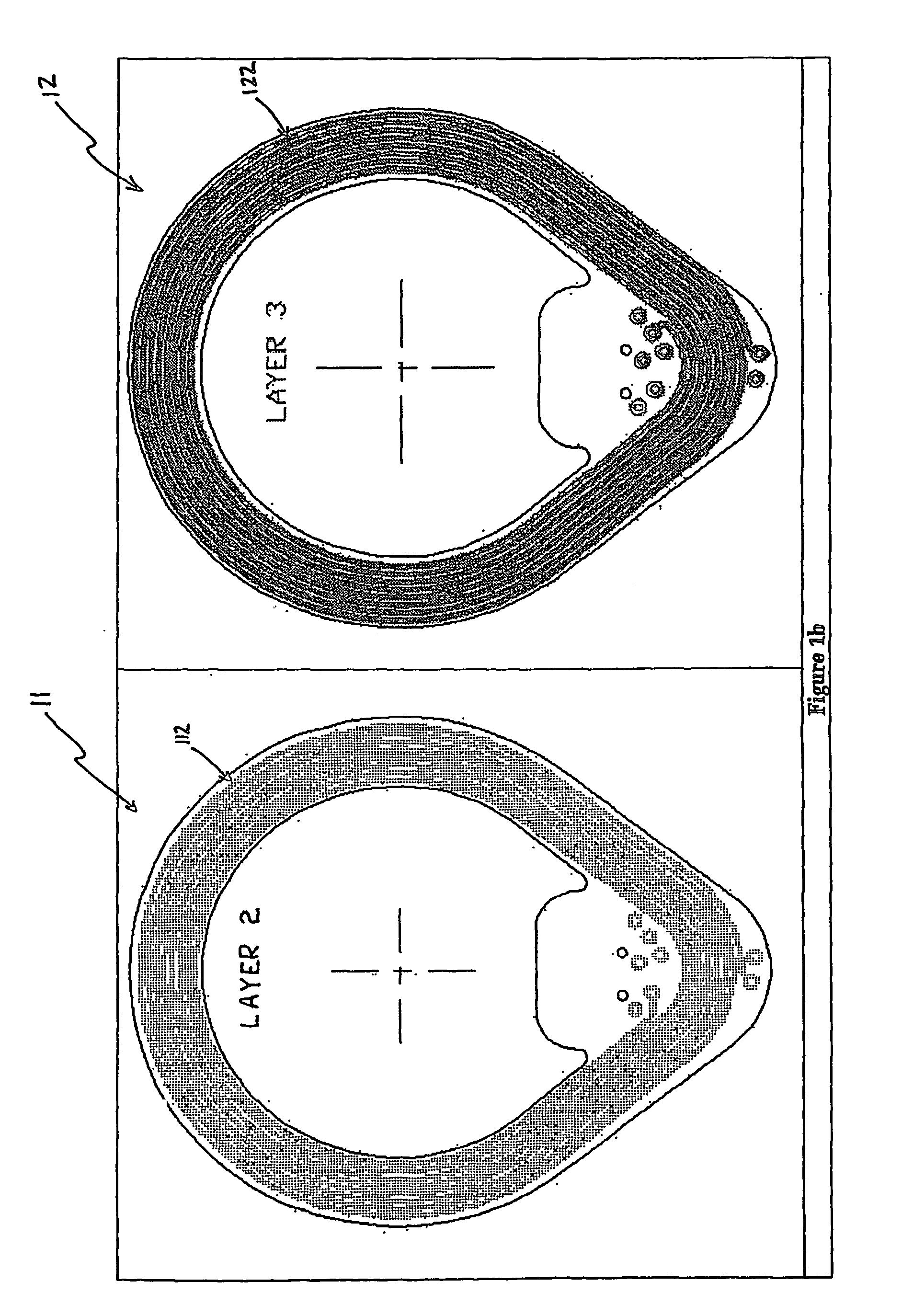
[0061]FIGS. 1a and 1b illustrate the layers of a transceiver for an auditory prosthesis in accordance with the present invention. The embodiment shown is based on standard PCB technology, although it will be appreciated that the present invention may be implemented otherwise. A low dielectric constant PCB material is used to reduce the shield-to-coil capacitance as well as the self-capacitance of the coil. A four layer PCB is used, where the top and bottom layers 10 and 13 are used for electrostatic shielding, and are electrically insulated from the transmission coil. The two inner layers 11 and 12 are used for the transmission inductor. FIGS. 1a and 1b depict the design of the different layers of a 16-turn coil.

[0062]The PCB material, layer thicknesses, copper track width and spacing are optimised to achieve maximum tuning frequency stability. This is to minimise the drift in tuning frequency due to varying stray capacitance, and also due to changes in temperature and humidity.

[006...


PUM


Abstract

The invention provides a tuned transmitter coil for transcutaneous transmission of power and information from an external component of an auditory prosthesis to an implanted receiver. A shield is provided in order to reduce a skin-to-coil capacitance, thereby improving tuning stability of the coil from one user to the next. A shield may also be provided in order to reduce electromagnetic interference.

Description

CROSS-REFERENCE TO RELATED APPLICATION[0001]This application is a National Phase Patent Application of International Application Number PCT / AU02 / 00640, filed on May 22, 2002, which claims priority of Australian Patent Application Number PR 5203, filed May 23, 2001.TECHNICAL FIELD[0002]The present invention relates to a transceiver coil for an auditory prosthesis, and to a system comprising such a transceiver coil. In particular, the present invention relates to a high performance PCB coil for forming a transcutaneous link in an auditory prosthesis.BACKGROUND ART[0003]In many people who are profoundly deaf, the reason for deafness is absence of, or destruction of, the hair cells in the cochlea which transduce acoustic signals into nerve impulses. These people are thus unable to derive suitable benefit from conventional hearing aid systems, no matter how loud the acoustic stimulus is made, because there is damage to or absence of the mechanism for nerve impulses to be generated from s...

Claims


Application Information

Patent Timeline
Patent Type & Authority Patents(United States)
IPC IPC(8): A61N1/00A61F2/18A61F11/00A61F11/04A61N1/36A61N1/372A61N1/375A61N1/378A61N2/04H01Q1/38H01Q1/52H01Q7/00H02J5/00
CPCA61N1/36032A61N1/37229A61N1/3787H01Q7/00H02J5/005A61N1/36036A61N1/36038H02J50/70H02J50/402H02J50/12H02J50/005H02J2310/23
Inventor IBRAHIM, IBRAHIM HANNA
Owner COCHLEAR LIMITED
Learn More