
Composite core conductors and method of making the same

Inactive Publication Date: 2012-07-26
GIFT TECH LLC
View PDF21 Cites 39 Cited by
  • Summary
  • Abstract
  • Description
  • Claims
  • Application Information

AI Technical Summary

Benefits of technology

[0008]In another exemplary embodiment, a method of forming an electrical cable for the transmission of electricity between power poles or towers is provided. The method includes pultruding a core having an inner portion formed from fiber reinforced resin, and an outer portion surrounding at least a portion of the inner portion, the outer portion formed from a fiber reinforced resin including a thermally conductive particulate material, where both the inner and outer portions of the core are pultruded simultaneously or sequentially, and surrounding the core with a conductor material. In one exemplary embodiment, forming the outer portion includes forming an outer layer having a radial thickness of at least ½ mil. In another exemplary embodiment, the thermally conductive particulate material includes aluminum. In yet another exemplary embodiment, the thermally conductive particulate material is mixed with a resin in a ratio of 20% to 50% by weight. In yet a further exemplary embodiment, the thermally conductive particulate material is of the same type as the conductor material. In another exemplary embodiment, the type of the resin forming the inner portion is different from the type of the resin forming the outer portion. In yet another exemplary embodiment, the method also includes adding at least one of carbon nanotubes and carbon black to at least the resin forming the outer portion. In one exemplary embodiment, at least one of carbon nanotubes and carbon black is added at a ratio relative to the at least the resin forming the outer portion. In another exemplary embodiment, the ratio is not greater than 3% by weight.
[0009]In another exemplary embodiment, an electrical cable for the transmission of electricity between power poles or towers is provided including a core formed from a fiber reinforced resin material reinforced by at least a first fiber, wherein at least a portion of the resin material forming at least an outer surface of the core includes a thermally conductive particulate material. The cable also includes and a conductor surrounding the core and the second fiber. In one exemplary embodiment, an outer surface portion of the core has a material thickness of at least ½ mil is formed from the resin including the conductive particulate material, and the outer surface portion is a layer surrounding a central portion. In another exemplary embodiment, the thermally conductive particulate material includes aluminum. In a further exemplary embodiment, the thermally conductive particulate material is mixed with a resin in a ratio of 20% to 50% by weight. In yet another exemplary embodiment, the thermally conductive particulate material is of the same type as the material forming the conductor. In yet a further exemplary embodiment, an outer surface portion is a layer formed from a first resin including the conductive particulate material and a central portion is formed from a second resin different from the first resin, wherein the outer surface portion surrounds the central portion. In one exemplary embodiment, the cable also includes at least one of carbon nanotubes and carbon black to the resin mixed with the resin.
[0010]In another exemplary embodiment, an ele

Problems solved by technology

However, when there is a failure of the conductor due to core failure, for example when the cable splits in two, the split cable ends may fall to the ground and initiate a hazardous condition.
Similarly, when exposed to high heat, the cores of such cables tend to expand and sag and may come in contact with objects on the ground, creating a hazardous situation.
Additionally, the operation of conductors at elevated temperature is inefficient in that their current carrying capacity is reduced.

Method used


Image

  • Composite core conductors and method of making the same
  • Composite core conductors and method of making the same
  • Composite core conductors and method of making the same

Examples


Embodiment Construction

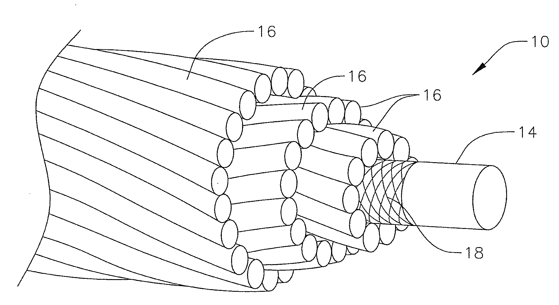
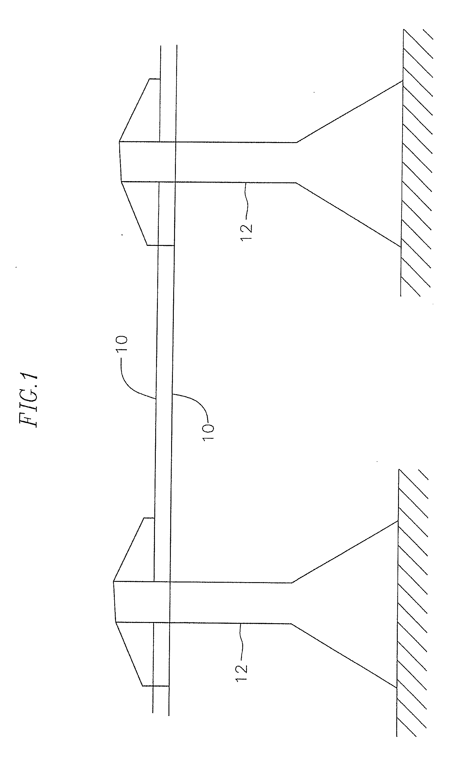
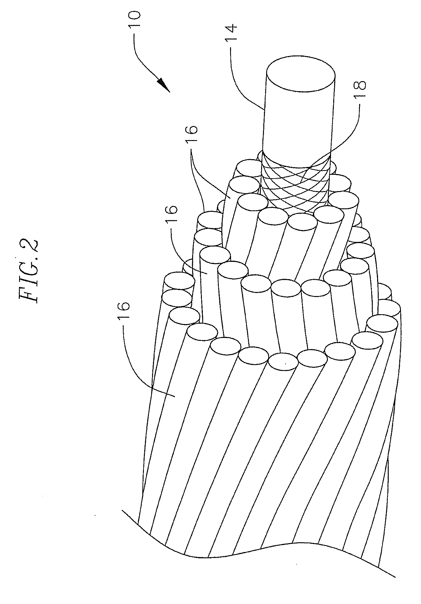
[0018]A composite core conductor cable 10 for the transmission of electricity between transmission towers 12 as for example shown in FIGS. 1 and 2, is disclosed U.S. Pat. No. 7,752,754, the entire content of which is fully incorporated herein by reference. A typical composite core conductor has a central core 14 formed from a composite material, such as a fiber reinforced plastic material, which is surrounded by at least one layer of a conductor 16, typically formed from strands of conductor material such as aluminum or copper, etc. for transmitting electricity. In an exemplary embodiment, the fiber reinforced plastic material includes a resin, as for example a thermoplastic resin such as polypropylene or polycarbonate resin or a thermosetting resin such as phenolic, epoxy, vinyl ester, polyester, or polyurethane resin, reinforced with reinforcing fibers (or fiber material) of glass, boron, carbon or the like, or any combination thereof. In an exemplary embodiment, the core is eithe...


PUM


Abstract

Electrical cables for the transmission of electricity between power poles or towers with at least one of a cooling feature and a fail safe feature and methods of producing the same.

Description

CROSS-REFERENCE TO RELATED APPLICATIONS[0001]This application claims the benefit of and priority to U.S. Provisional Patent Application No. 61 / 435,725, filed on Jan. 24, 2011, and on U.S. Provisional Patent Application No. 61 / 450,525, filed on Mar. 8, 2011, the contents of both of which are hereby fully incorporated herein by reference.BACKGROUND OF THE INVENTION[0002]Composite core conductor cables have a composite core supporting a conductor. Such cables have many advantages. However, when there is a failure of the conductor due to core failure, for example when the cable splits in two, the split cable ends may fall to the ground and initiate a hazardous condition. Similarly, when exposed to high heat, the cores of such cables tend to expand and sag and may come in contact with objects on the ground, creating a hazardous situation. Additionally, the operation of conductors at elevated temperature is inefficient in that their current carrying capacity is reduced. Thus, composite co...

Claims


Application Information

Patent Timeline
IPC IPC(8): H01B9/00B05D5/12
CPCH01B5/105
Inventor WINTERHALTER, MICHAELMCQUARRIE, TERRY
Owner GIFT TECH LLC
Learn More