
Cooling module for LED lamp

a technology of led lamps and cooling modules, which is applied in the direction of lighting and heating apparatus, tubular elements, point-like light sources, etc., can solve the problems of affecting the life and performance of leds, and the cooling efficiency is still not enough for high power/watt leds, so as to facilitate lateral air convection, reduce the overall weight of the cooling module, and increase the cooling area

Inactive Publication Date: 2012-07-26
CELSIA TECH TAIWAN INC
View PDF15 Cites 7 Cited by
  • Summary
  • Abstract
  • Description
  • Claims
  • Application Information

AI Technical Summary

Benefits of technology

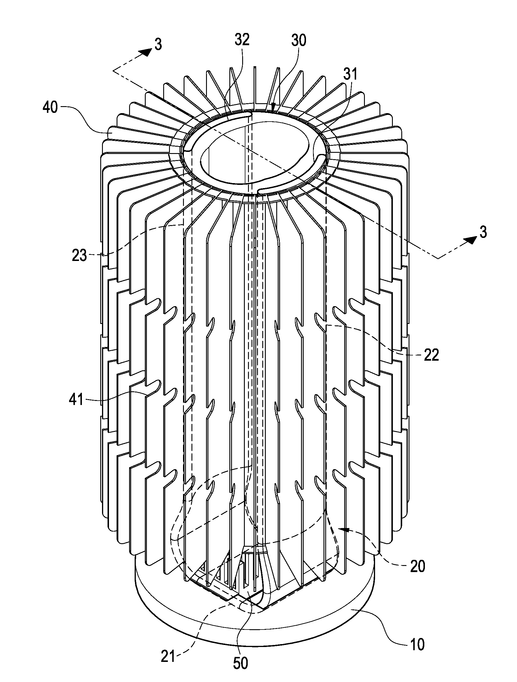
[0007]The present invention provides a cooling module for an LED lamp. The direct thermal contact between its cooling fins and the hollow column and the thermostatic plate can dissipate the heat generated by the LED lamp more efficiently.
[0009]The present invention allows each of the cooling fins to be manufactured through thin-sheet stamping and then be connected to the thermostatic plate and the hollow column. This not only greatly minimizes the overall weight of the cooling module, but also increases the cooling area per unit volume. Furthermore, the heat conducting base has a container trough to connect to and fix the thermostatic plate. The through opening further allows the thermostatic plate to directly conduct heat away from the LED heat source. In addition, each of the cooling fins has some through troughs. These through troughs will facilitate lateral air convection between each two adjacent air passages.

Problems solved by technology

However, temperature variation may affect an LED's life and performance.
Although the aforementioned structure is good for cooling, its cooling efficiency is still not enough for high power / watts LEDs.

Method used


Image

  • Cooling module for LED lamp
  • Cooling module for LED lamp
  • Cooling module for LED lamp

Examples


Embodiment Construction

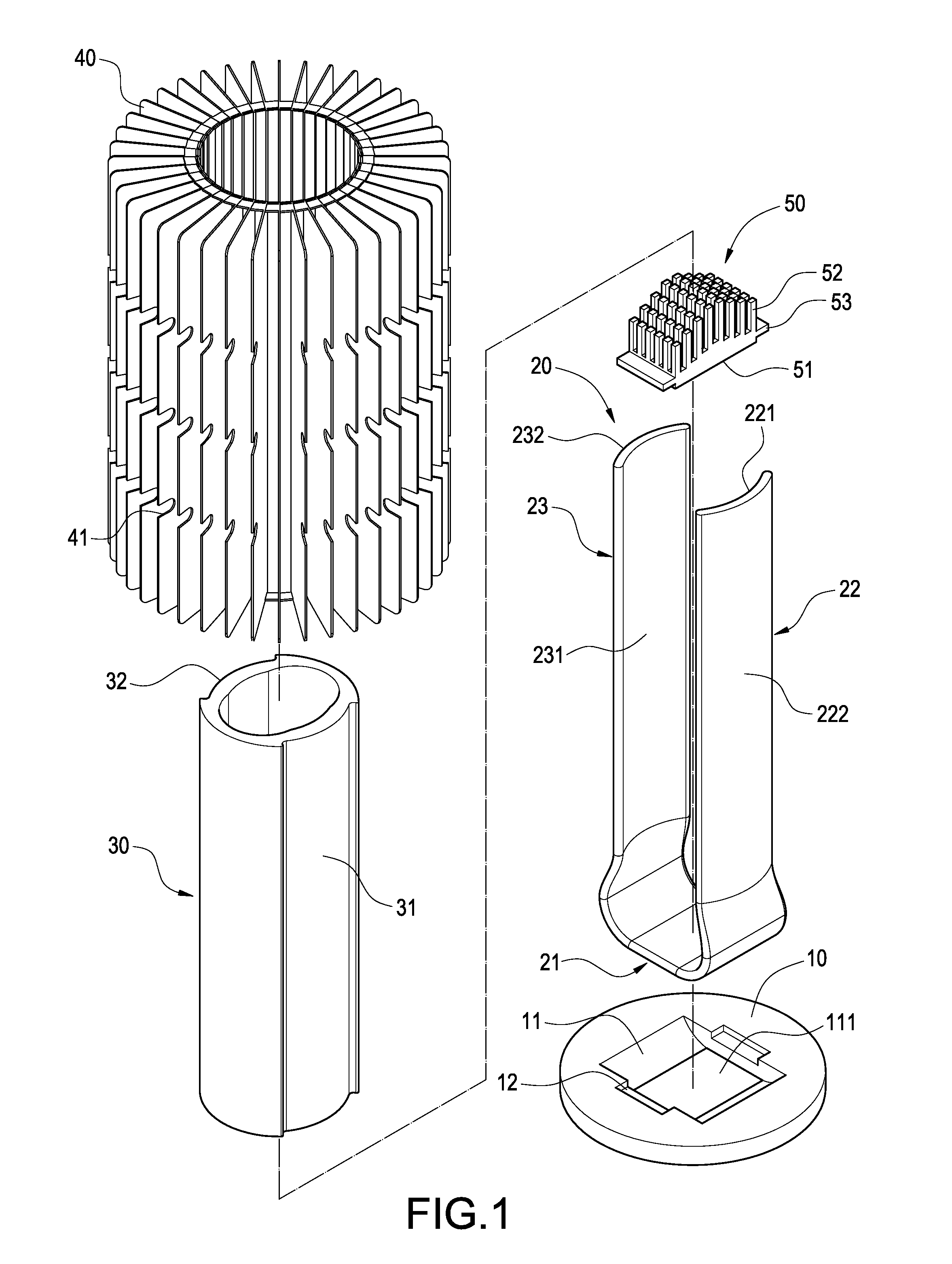
[0016]FIG. 1 to FIG. 4 shows a cooling module for an LED lamp according to an embodiment of the present invention. The cooling module of the embodiment primarily includes a heat conducting base 10, a thermostatic plate 20, a hollow column 30, and a plurality of cooling fins 40.

[0017]The heat conducting base 10 is made of metal such as aluminum, copper, or their alloy. Generally, the shape of the heat conducting base 10 is like a circular plate. A middle part of the plate has a rectangular container trough 11. A through opening 111 is formed on the bottom of the container trough 11. A step 12 is set on each of the two lateral sides of the container trough 11.

[0018]The thermostatic plate 20 of this embodiment is a vapor chamber, the vacuum chamber of which contains components such as capillary structure and working fluid. The gas-liquid phase change of the working fluid can achieve heat conduction. Furthermore, the capillary structure can help the working fluid to flow-back and hence ...


PUM


Abstract

A cooling module for an LED lamp includes a thermostatic plate, a hollow column, and a plurality of cooling fins. The thermostatic plate has an evaporating segment and a pair of condensing segments extending from the evaporating segment. The outer surface of the hollow column has a pair of grooves corresponding to each other. The condensing segments of the thermostatic plate are buried in the grooves. The cooling fins surround and thermally contact the outer rim of the hollow column and the condensing segments.

Description

BACKGROUND[0001]1. Technical Field[0002]The present invention relates to cooling modules. More particularly, the present invention relates to cooling modules for light emitting diode (“LED”) lamps.[0003]2. Related Art[0004]Light emitting diodes (“LEDs”) have the characteristics of low power consumption, high energy efficiency, long lifetime, small volume, and fast response. Because of these characteristics, LEDs have been replacing traditional light bulbs and been used in different lighting instruments (i.e. lamps). However, temperature variation may affect an LED's life and performance. Therefore, an LED's cooling module must have optimal arrangement.[0005]A conventional LED lamp cooling module has a hollow column and a thermostatic plate. The hollow column has a ring-shaped inner wall. The thermostatic plate has an evaporating segment and two condensing segments corresponding to each other. The two condensing segments lie inside and across the hollow column and contact with the ho...

Claims


Application Information

Patent Timeline
IPC IPC(8): F28F1/14
CPCF28F1/14F21V29/006F21K9/00F28D15/0233F28D15/0275F21V29/89F21Y2101/02F21V29/717F21V29/773F21V29/81F21V29/83F28F1/10F21Y2105/10F21Y2115/10F21V29/77
Inventor MEYER, IV, GEORGE ANTHONYSUN, CHIEN-HUNGCHEN, CHIEH-PING
Owner CELSIA TECH TAIWAN INC
Learn More