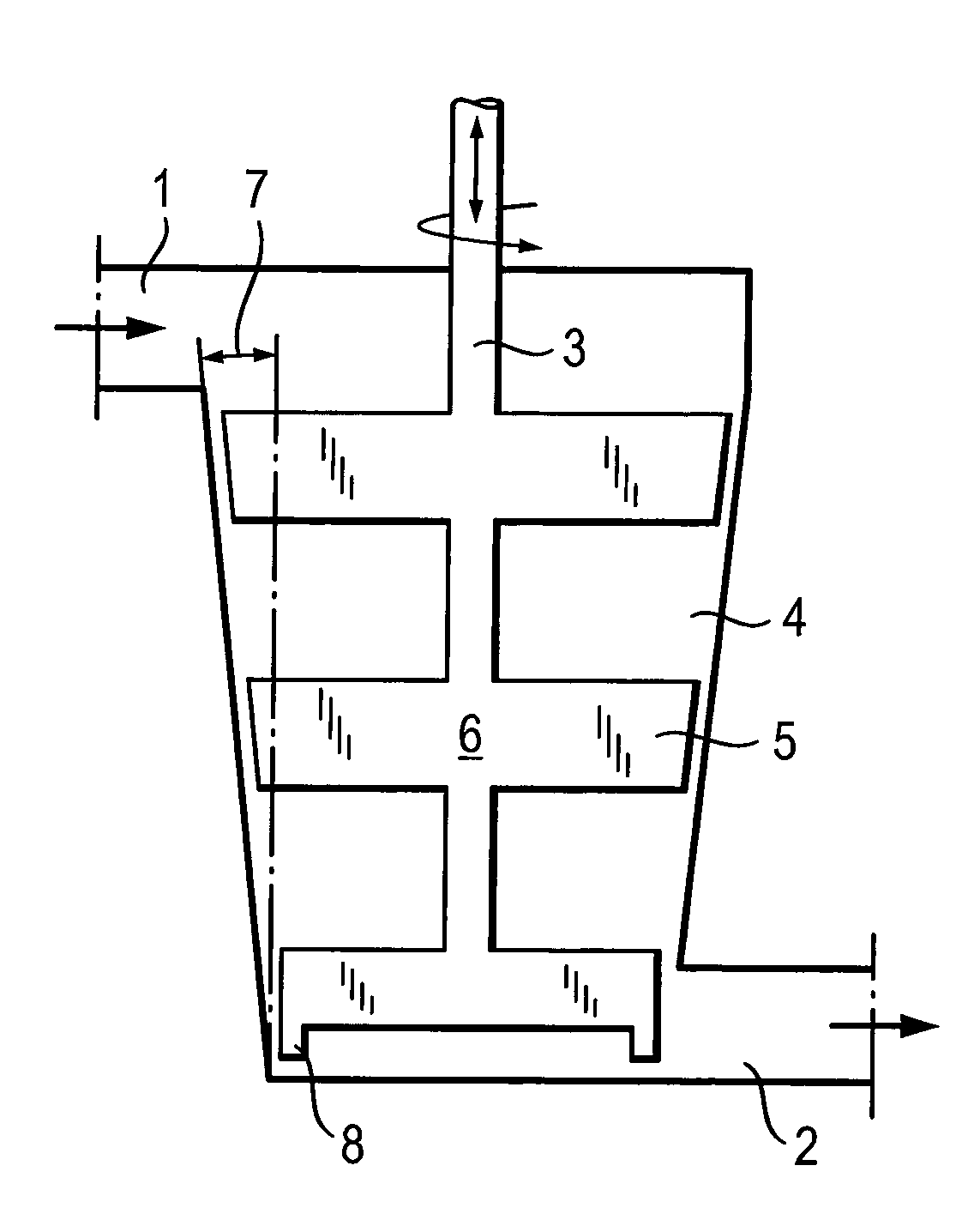
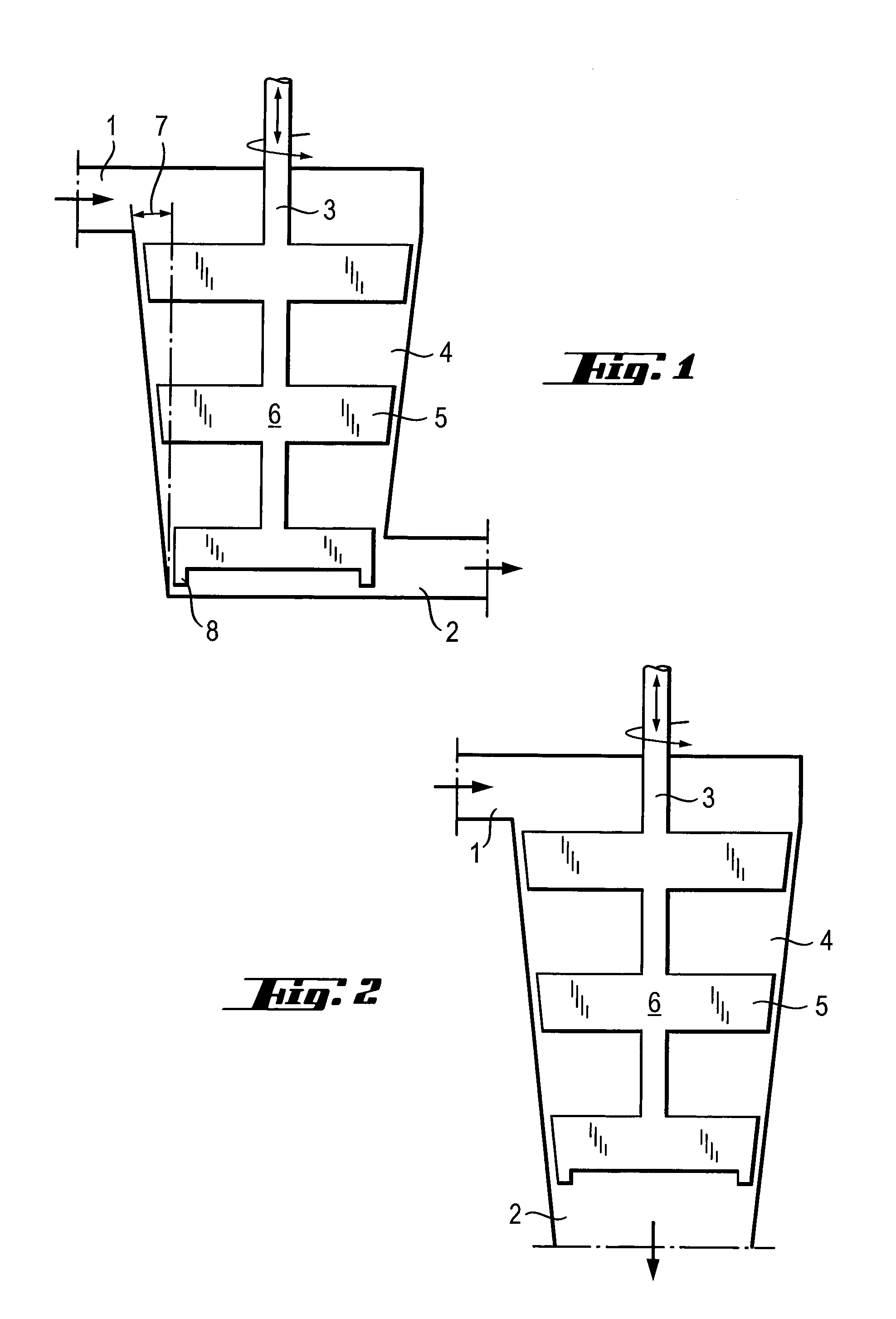
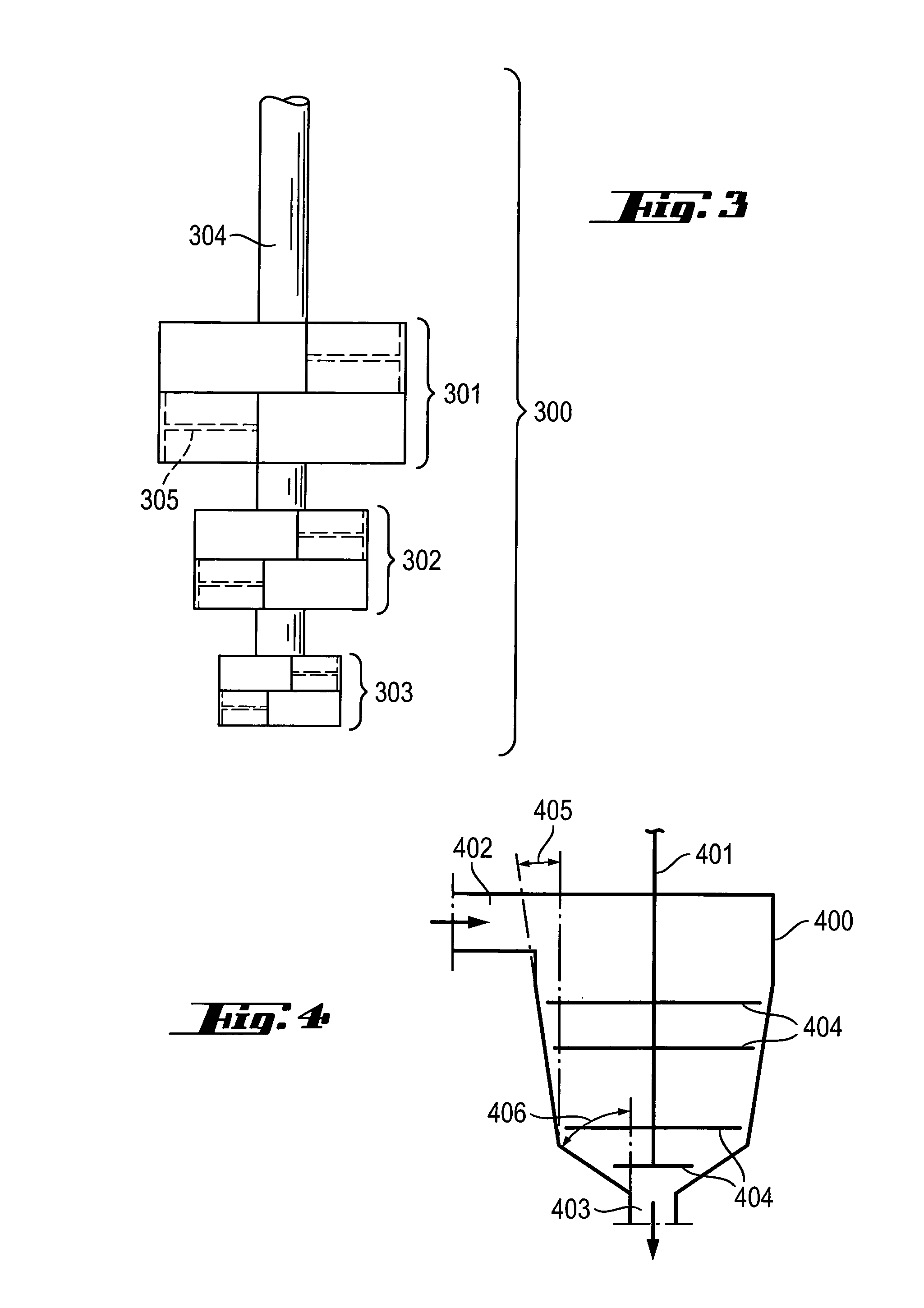
[0103]In order to adapt the stirring parameters during operation, the speed of the stirrer can be changed. It is an
advantage of the present invention that the
processing parameters can be changed during operation in addition by axial movement of the shaft. Since the shape of the stirring chamber is conical, axial movement will increase (or decrease, respectively) the distance between the stirring chamber and the stirrer. If the stirrer is moved upward and the distance between the stirrer and the stirring chamber is increased, the shear applied to the
molten glass is decreased, if the stirrer is moved downward and the distance between the stirrer and the stirring chamber is decreased, the shear applied to the
molten glass is increased. If desired, the speed of the stirrer can be increased or decreased at the same time.
[0104]This change of the
processing parameters can be used to adapt the apparatus to different products or to varying
viscosity of the
molten glass and in this case the processing parameters are adapted when the product is changed, or a better adjustment of different processing parameters to the optimum result can be achieved.
[0105]However, axial movement of the stirrer can also be used to improve the mixing during normal operation, for example by effecting the axial movement periodically or aperiodically during operation.
[0106]Since molten glass to which both the stirrer and the apparatus of the invention are exposed partially or entirely may well exceed 1000° C., it is evident that the materials of the stirrer and the apparatus of the invention are made of must be capable of withstanding such high temperatures. Such materials are
refractory metals, in particular
tantalum,
niobium,
tungsten,
molybdenum,
iridium,
rhodium,
palladium and
platinum. As mentioned above, the stirring chamber, the stirrer or parts thereof may also be made of two different materials, like a material in the center covered by a different material, such as a material that is cheap in the center and covered by a more expensive material exhibiting e.g. a higher
corrosion resistance. For example, parts of the stirrer and / or the apparatus can be made of
molybdenum, and thereafter coated with another refractory
metal comprising
platinum. The
molybdenum core provides shape and
mechanical strength to the stirrer, whereas the
platinum outer layer provides wear and
corrosion resistance. In other embodiments, the core of the stirrer may be formed entirely of platinum, or a platinum
alloy, such as a platinum-
rhodium alloy.
Platinum in particular is a desirable refractory
metal for glass stirring applications because of its high
melting point,
corrosion resistance and workability. Most preferred are ODS (
Oxide Dispersion Strengthened) platinum, platinum-
rhodium alloys or combinations thereof.
Oxide dispersion strengthened platinum is a preferred material, in particular zirconia dispersion strengthened platinum is preferred, but e.g. yttria dispersion strengthened platinum is also suitable. Preparation of these materials is known and described, for example, in EP 1781830 and EP 1295954, which are incorporated by reference for all useful purposes. Parts of the apparatus may also be made of a
ceramic and covered by platinum. For example, the stirring chamber can be made of platinum and embedded into a
ceramic material as support.
[0107]Nonetheless, platinum, or even platinum rhodium alloys, are not immune to
erosion during high temperature stirring processes. In order to reduce wear of the stirrer, it is advantageous if the stirring elements define a plurality of grooves in an outside surface thereof. These modifications will produce a static or quasi-static layer of molten glass on surfaces of the stirrer. In particular, the distal end portions of the stirring elements may comprise grooves or holes in the outside surface thereof. Preferably, grooves are perpendicular to the flow of glass over the surface comprising the grooves, but may vary depending upon the design of the stirring elements. Grooves trap the viscous molten glass, creating a layer of static or quasi static glass over the end portions of the stirring elements. Whereas a
smooth surface as used in conventional stirrers leads to flow related
erosion of the surface, a static layer of molten glass according to the present embodiment has the effect of forming a protective layer of glass over the surface of the stirring element(s), thereby reducing stirring element erosion by reducing the flow of glass over the surface of the
impeller. Grooves may be periodic or non-periodic in their arrangement. They may be rectangular in shape, with sharp corners defining the groove, or exhibit rounded corners and / or arcuate or angled walls. The grooves may also vary in size, i.e. the width of the grooves varies. A stirring element may comprise all or some of the modifications to reduce wear, e.g. a portion of the grooves being non-periodic or periodic, varying width and varying groove wall shapes.
[0108]In combination therewith or in substitution thereof, an
iridium layer can be applied on portions of the stirrer to reduce wear as described in WO 2008 / 088432. In combination or substitution therewith, said grooves or said
iridium layer may as well be applied. In the apparatus according to the invention the inner surface of the stirring chamber preferably comprises a plurality of grooves, said grooves being preferably roughly perpendicular with the axis of rotation of said shaft. This also reduces the wear of the stirrer.


