Rotary anode for a rotary anode x-ray tube and method for manufacturing a rotary anode

Active Publication Date: 2012-06-28
PLANSEE SE
View PDF1 Cites 2 Cited by
  • Summary
  • Abstract
  • Description
  • Claims
  • Application Information

AI Technical Summary

Benefits of technology

[0026]To this purpose, an electron beam emitted by a cathode being part of the X-ray tube is used. It is directed to the anode disc at the focal track to heat the supporting portion in this area. By this means, the heating can be performed in a very simple and precise manner exactly to those areas where the re-crystallization process has to be carried out for obtaining the thermal stability of the supporting portion of the anode disc strived for. As this process step will take place after having evacuated the X-ray tube, the anode disc automatically is prevented from thermal oxidation. However, the electron beam usually will have to be of higher intensity than for regular operation of the X-ray tube.
[0028]The pseudo-rotary-X-ray tube in this context can be understood as a production apparatus similar to an X-ray tube, in which the rotary anode is fixed only during manufacture for fabrication purposes. Thus, the manufacturing steps described are taking place in this production apparatus, and an overload of the construction elements of the X-ray tube during the manufacture is avoided.
[0030]In this embodiment, the heating again is performed by an electron beam; however, the electron beam is now directed to a backside of the supporting portion underneath the focal track. Such, especially an excessive heating of the anode portion at the focal track and consequently an erosion of the material of the anode portion caused by this heating is avoided.
[0035]Such, according to this embodiment, the anode disc is forged disc with a certain distribution of the degree of deformation, that way that the degree of deformation is higher on the inner diameter than on the outer diameter, and a uniform annealing temperature is applied afterwards to the anode disc, for example in a furnace. This leads to a simpler and more cost-saving fabrication process.
[0037]The invention is applicable for every anode disc of a rotary anode X-ray tube. It is of particular advantage in case of high-power rotary anode X-ray tubes with a high power density and a controlled heat flow through the anode disc.

Problems solved by technology

However, in modern rotary anode X-ray tubes, the rotary anode is subjected to extreme thermal and mechanical loads during operation of the rotary anode X-ray tube.
This may have unwanted impacts on the material of the supporting portion of the anode disc, and especially may lead to unwanted changes of the material properties of the material of the supporting portion of the anode disc.

Method used


Image

  • Rotary anode for a rotary anode x-ray tube and method for manufacturing a rotary anode
  • Rotary anode for a rotary anode x-ray tube and method for manufacturing a rotary anode
  • Rotary anode for a rotary anode x-ray tube and method for manufacturing a rotary anode

Examples


Embodiment Construction

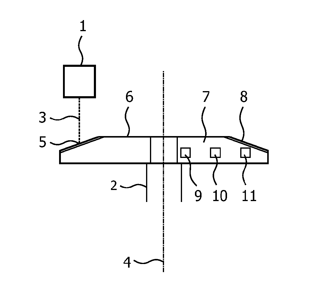
[0048]In FIG. 1, a schematic cross-sectional view of some essential inner construction elements of a rotary anode X-ray tube is shown, comprising a cathode 1 and a rotary anode 2. During operation of the rotary anode X-ray tube, an electron beam 3 is emitted from the cathode 1 and directed to the rotary anode 2, which is rotated around an rotational axis 4. The electron beam 3 hits the rotary anode 2 at a focal track 5.

[0049]The rotary anode 2 comprises an anode disc 6, which, in turn, comprises a supporting portion 7 made from a molybdenum alloy, for example of the so-called “TZM”. In the vicinity of an outer diameter at the focal track 5 of the anode disc 6, an anode portion 8, also denoted as target layer, is mounted to the supporting portion 7.

[0050]In FIG. 1, further three spots are marked in the cross-section of the supporting portion 7 of the anode disc 6: a first spot 9 in the area of an inner diameter of the anode disc 6, a second spot 10 at an intermediate point between th...


PUM


Abstract

A rotary anode for a rotary anode X-ray tube has an anode disc with a supporting portion. A focal track is located in the vicinity of an outer diameter of the anode disc. The supporting portion has inhomogeneous material properties along a radial coordinate of the anode disc to provide a high mechanical load capacity in the area of an inner diameter of the anode disc and a high thermal load capacity at the focal track. These measures provide for a rotary anode for a rotary anode X-ray tube that meets the extreme thermal and mechanical loads during operation. Further, a method for manufacturing such a rotary anode is described as well.

Description

FIELD OF THE INVENTION[0001]The invention is related to a rotary anode for a rotary anode X-ray tube. The invention is further related to a method for manufacturing a rotary anode for a rotary anode X-ray tube.BACKGROUND OF THE INVENTION[0002]From U.S. Pat. No. 3,735,458 a double-layer rotary anode and a method for manufacturing such a double-layer rotary anode from a tungsten anode portion and a supporting portion of a cast molybdenum alloy is known.[0003]As a molybdenum alloy for the supporting portion, a material known under the trade name “TZM” is used. Besides molybdenum, this material contains titanium, zirconium and carbon. It is satisfactory workable by temperature and deformation treatments already carried out in the metallurgical factory. The admixtures of titanium and zirconium in the molybdenum lower the melting point so that this material can be cast and the re-crystallization temperature is raised to 1,800° C. Thus the increase in mechanical strength achieved in this m...

Claims


Application Information

Patent Timeline
IPC IPC(8): H01J35/10H01J9/02
CPCH01J35/108H01J2235/085H01J2235/081
Inventor HOVE, ULRICHTERLETSKA, ZORYANABATHE, CHRISTOPHRODHAMMER, PETERSCHATTE, JURGENGLATZ, WOLFGANGMULLER, THOMAS
Owner PLANSEE SE
Why Eureka
Try Eureka