
Modal discriminating and linearly polarized fiber lasers

Inactive Publication Date: 2004-10-05
PC PHOTONICS CORP
View PDF15 Cites 0 Cited by
  • Summary
  • Abstract
  • Description
  • Claims
  • Application Information

AI Technical Summary

Benefits of technology

Objects of the invention include provision of a multicore phase-locked fiber laser array in which the fundamental, in-phase supermode is dominant, thereby emitting output power in a high-brightness and diffraction-limited laser beam; provision of a linearly polarized laser output from a clad-pumped, phase-locked fiber laser array; and provision of high laser power without high power densities which could damage the rare earth-doped fiber.
According to the present invention, a plurality of cores doped with a rare earth lasing ion, within a common pump cladding, includes a central core and additional cores disposed outwardly of said central core, and having either or both of (a) an oblong cross section, thereby to provide a linearly polarized output laser beam, or (b) a mode discriminating characteristic, such as index of refraction, gain or cross sectional dimension, which is graded and being lower for the outward cores than the central cores, thereby to transfer laser power coherently into a bright laser beam of the fundamental in-phase supermode. According further to the invention, instead of an array of oblong cores, a single oblong core in a very large cladding may be utilized to provide a linearly polarized output beam. According to the invention further, utilization of a graded modal discrimination characteristic provides the ability to separate the cores by as much as five-fold more than in the prior art, such as with center-to-center spacings of 15 to 50 microns, whereby the laser power in a single bright beam can be spread over a greater area and thereby provide very high power without prohibitively high power densities.

Problems solved by technology

Both of these methods are useful only for low power lasers; for high power lasers, they are neither effective nor practical because a very high penalty must be paid by trading off output power for modal purity.
Use of polarization filters necessarily results in severe power reduction and loss of efficiency.

Method used


Image

  • Modal discriminating and linearly polarized fiber lasers
  • Modal discriminating and linearly polarized fiber lasers
  • Modal discriminating and linearly polarized fiber lasers

Examples


Embodiment Construction

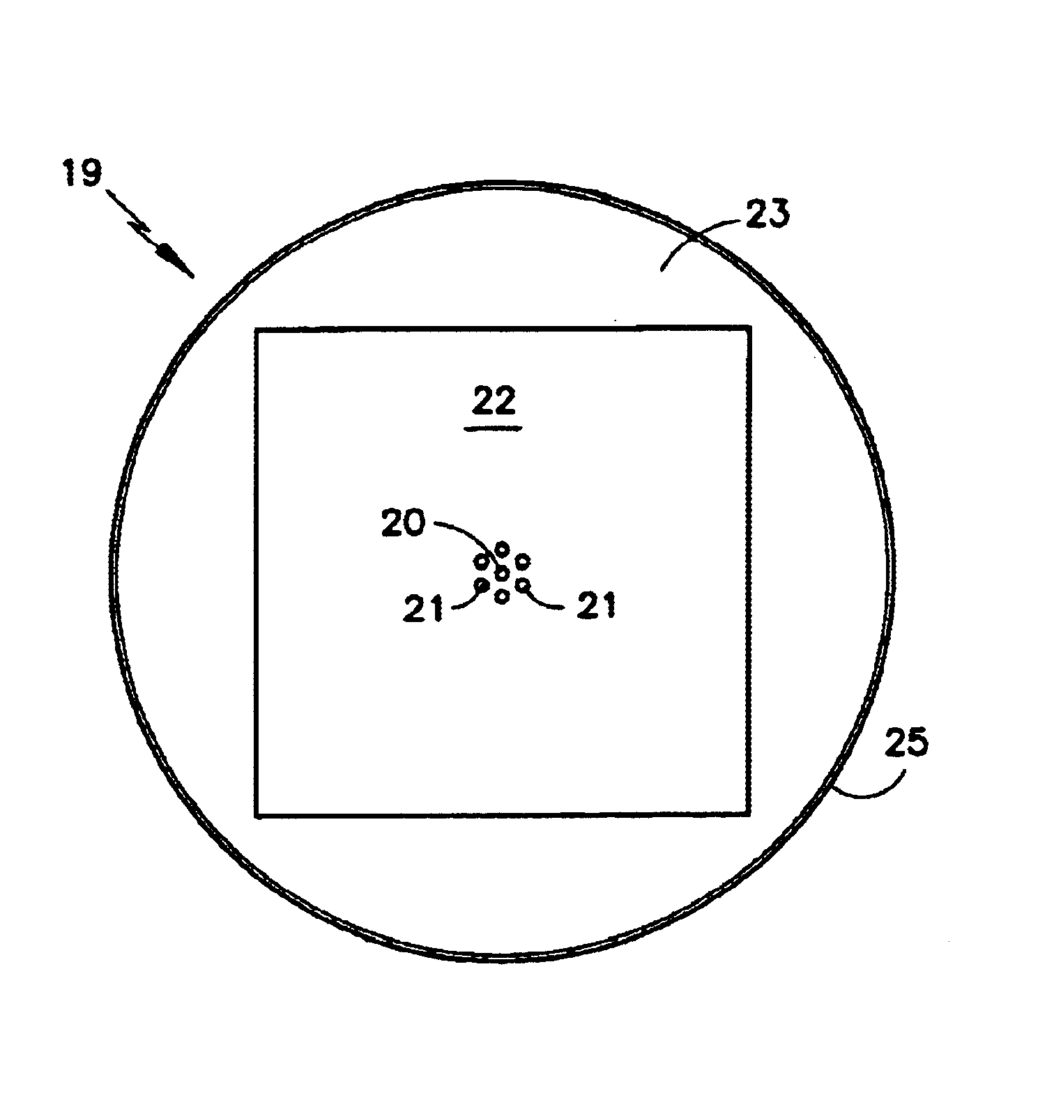
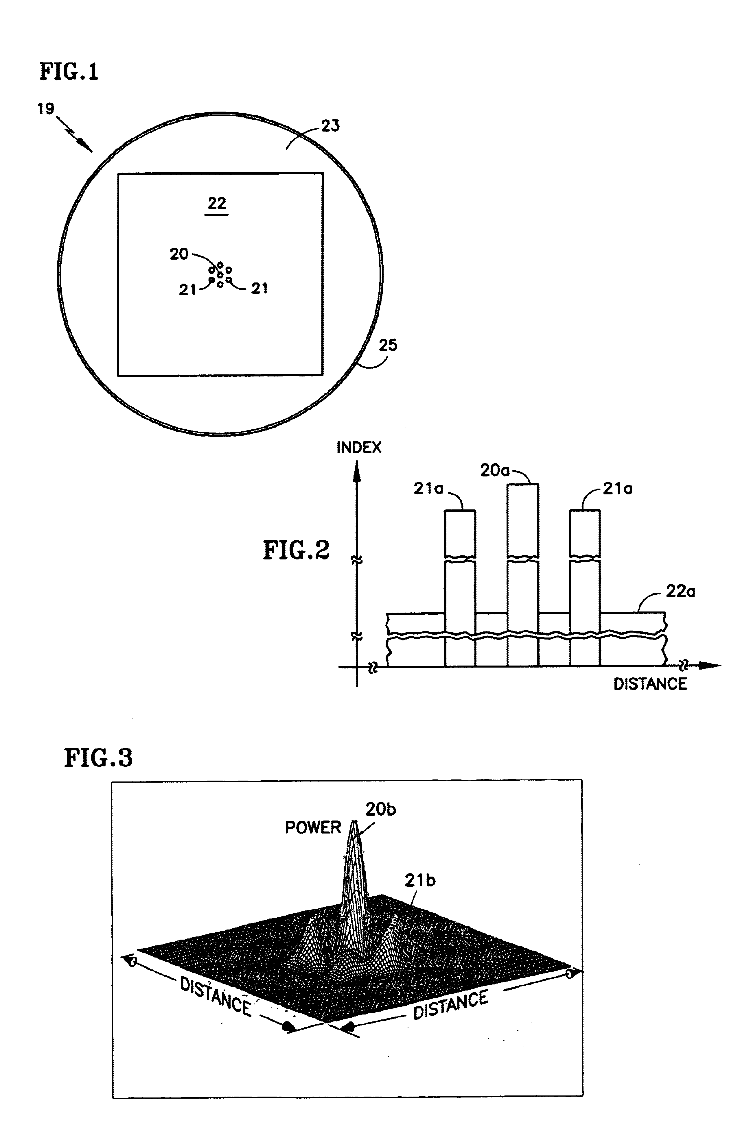
Referring to FIG. 1, a loser fiber 19 comprises a plurality of doped fiber cores, including a central core 20 and a ring of six cores 21 forming an isometric pattern. The cores 20, 21 are surrounded by an inner, pump cladding 22 which is within an outer cladding 23, all of which is surrounded by a protective coating 25. According to the invention, the cores 21 are provided with an index of refraction which is less than the index of refraction of the core 20, as illustrated by the bars 21a end 20a, respectively, in FIG. 2. For example, the ring of FIG. 1 may have a V-value of 1.6 whereas the central core 27 may have a V-value of 2.4. Naturally, the inner, pump cladding 22 has a much lower index of refraction as illustrated by the bar 22a. The difference in the index of refraction of the cores 21 from that of the core 20 need only be on the order of 1% in order to accomplish approximately a two-fold increase in the power (20b in FIG. 3) of the in-phase fundamental supermode, in contra...


PUM


Abstract

A single core 35, 50 or a plurality of cores arranged in rings 21, 28, 29 around a central core 20, 27, or in an array 42, are provided with either or both of (a) a modal discrimination characteristic, including gain, index of refraction and cross sectional area, which is greatest in the center of the core or the array, and lowers outwardly therefrom, and (b) an oblong cross section, thereby to provide either or both of (c) a bright laser beam of the fundamental in-phase supermode, and / or (d) a linearly polarized output beam.

Description

This invention relates to phase-locked fiber lasers that provide diffraction limited, high brightness and / or linearly polarized output laser beams, employing modal discriminating multiple cores and / or single or multiple oblong cores.If the cores of a multi-core fiber laser array are configured in a hexagonal series of isometric rings, the evanescent-wave coupling among all adjacent emitters provides spontaneous phase locking so as to combine the power of all supermodes coherently into a single bright beam centered on the fiber axis, as is described in U.S. Pat. No. 6,031,850. Because a very strong evanescent-wave interaction over a very long fiber length, the double-clad multi-core fiber laser array is naturally phase-locked to emit all supermodes co-existing in the structure. In the case of a single isometric ring of six cores surrounding a central core, there exists five supermodes. In a large multicore phase-locked fiber laser system containing many isometric rings, there exists ...

Claims


Application Information

Patent Timeline
IPC IPC(8): H01S3/30H01S3/067H01S3/094
CPCH01S3/06708H01S3/094003H01S3/06729
Inventor CHEO, PETER K.KING, GEORGE G.
Owner PC PHOTONICS CORP
Learn More