Method of and Apparatus for Selective Catalytic NOx Reduction in a Power Boiler

a technology of catalytic nox and power boiler, which is applied in the direction of emission prevention, separation processes, flue gas purification components, etc., can solve the problems of permanent catalyst activity loss, reducing the effectiveness of the process, and affecting the efficiency of the process

Inactive Publication Date: 2012-06-28
FOSTER WHEELER NORTH AMERICA CORP
View PDF7 Cites 21 Cited by
  • Summary
  • Abstract
  • Description
  • Claims
  • Application Information

AI Technical Summary

Benefits of technology

[0016]An object of the present invention is to provide a method of selective catalytic NOX reduction in a power boiler by which problems of the prior art described above can be minimized.

Problems solved by technology

This can cause permanent catalyst activity loss.
Above 400° C., ammonia may dissociate, reducing the effectiveness of the process.
If temperatures exceed about 450° C., the catalyst activity might be permanently impaired due to sintering.
In addition to the problem addressed by U.S. Pat. No. 5,555,849, it has been observed that, especially in retrofit installations of an NOX catalyst in an existing power boiler, the flue gas temperature at the NOX catalyst may, especially at high loads, tend to be too high.
This method, however, increases the feed water temperature and, if the temperature rises close to the saturation temperature of the steam drum, it will have negative effects on the water circulation of the boiler and ultimately, reduce boiler performance.

Method used


Image

  • Method of and Apparatus for Selective Catalytic NOx Reduction in a Power Boiler
  • Method of and Apparatus for Selective Catalytic NOx Reduction in a Power Boiler
  • Method of and Apparatus for Selective Catalytic NOx Reduction in a Power Boiler

Examples


Embodiment Construction

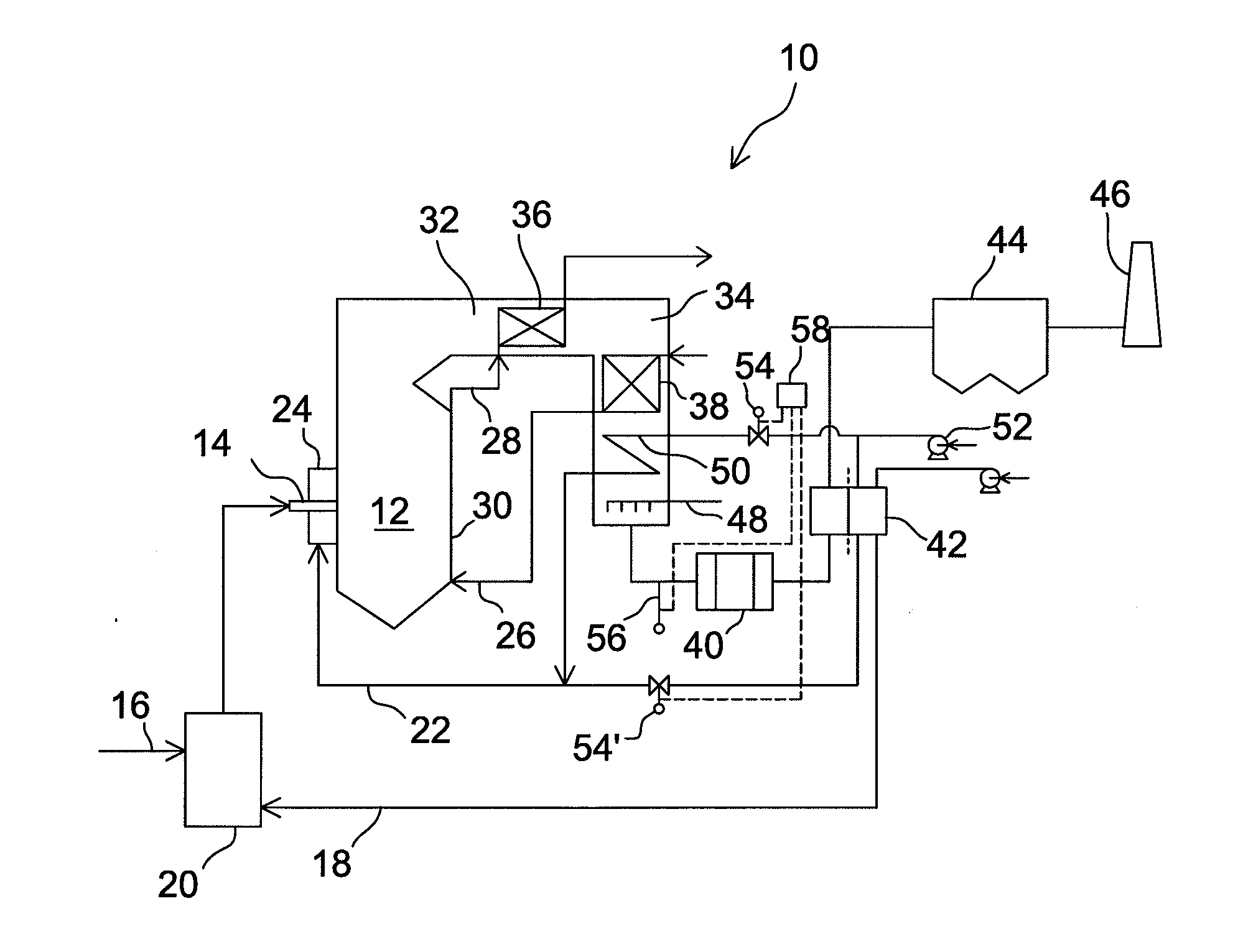
[0026]FIG. 1 is a schematic diagram of a pulverized coal combusting power boiler 10 in accordance with the present invention. The boiler comprises a furnace 12 with a burner 14 for injecting a mixture of pulverized coal 16 and primary air 18 from a coal mill 20 to the furnace. Usually, a power boiler comprises multiple burners but, for the sake of simplicity, only one burner is shown in FIG. 1. The fuel is combusted in the furnace with the primary air and secondary air 22, injected to the furnace via a windbox 24 adjacent to the burner, and hot flue gas is generated. The combustion may in practice be completed by tertiary air and / or overfire air injected in the furnace downstream of the burners, but, for the sake of simplicity, injection of tertiary air and / or overfire air is not shown in FIG. 1. Generated hot flue gases rise within the furnace, giving up a portion of their energy in evaporator surfaces 30 at the walls of the furnace to evaporate feed water 26 to steam 28. The flue ...


PUM

PropertyMeasurementUnit
temperaturesaaaaaaaaaa
temperatureaaaaaaaaaa

Abstract

A method of selective catalytic NOX reduction in a power boiler and a power boiler with selective catalytic NOX reduction. Fuel is combusted in a furnace of the boiler and a flue gas stream that includes NOX is generated. The flue gas stream is conducted from the furnace along a flue gas channel to a stack. The flue gas stream is cooled in a heat recovery area, including an economizer section, arranged in the flue gas channel. At least a portion of the NOX is reduced to N2 in an NOX catalyst arranged in the flue gas channel downstream of the economizer section. The flue gas is further cooled, and heated air is generated in a gas-to-air heater arranged in the flue gas channel downstream of the economizer section and upstream of the NOX catalyst. The gas-to-air heater may be a tubular air heater or a heat exchanger with a recirculating heat transfer fluid.

Description

BACKGROUND OF THE INVENTION[0001]1. Field of the Invention[0002]The present invention relates to a method of and a system for selective catalytic NOx reduction (SCR) in a solid or a liquid hydrocarbon fuel firing power boiler. More particularly, the present invention relates to controlling the temperature of a flue gas entering an NOx catalyst of the boiler.[0003]2. Description of the Related Art[0004]Oxides of nitrogen, also known as NOX, contribute to the generation of acid rain and smog. Due to environmental regulations demanding that NOX emissions be maintained at acceptable levels, the reduction of NOX both during and after the combustion process is of a major concern in the design and operation of modern power plants.[0005]Oxides of nitrogen are a byproduct of the combustion of solid and liquid hydrocarbon fuels, such as pulverized coal or oil, and are found in two main forms. If the nitrogen originates from the combustion air, the NOX is referred to as “thermal NOX”. Thermal ...

Claims


Application Information

Patent Timeline
Patent Type & Authority Applications(United States)
IPC IPC(8): F23J15/02F23N3/00F23L15/02
CPCB01D53/8631F23J15/006B01D2251/2067B01D2255/20707B01D2255/20738B01D2258/0283F01K3/247F01K13/00F22B1/1876F22B37/008F23J15/06F23J2215/10F23J2219/10F23L15/045Y02E20/12B01D2251/2062Y02E20/34F22B1/18F22B37/00
Inventor GREENHUT, DAVIDELSTON, JOHNMAZZOLLA, MICHAELEDWARDS, ALFRED
Owner FOSTER WHEELER NORTH AMERICA CORP
Why Eureka
Try Eureka