Eureka AIR delivers breakthrough ideas for toughest innovation challenges, trusted by R&D personnel around the world.

Device and method for reducing spread of microorganisms and airborne health hazardous matter and/or for protection from microorganisms and airborne health hazardous matter

a technology of microorganisms and airborne health hazards, applied in the direction of filtration separation, medical science, light and heating equipment, etc., can solve the problems of reducing the effective airflow towards the exhaust opening, and reducing the effective face area of the exhaust. , to achieve the effect of minimising the risk and minimising the smell or quality problems

Inactive Publication Date: 2012-08-09
DANMARKS TEKNISKE UNIV
View PDF5 Cites 63 Cited by
  • Summary
  • Abstract
  • Description
  • Claims
  • Application Information

AI Technical Summary

Benefits of technology

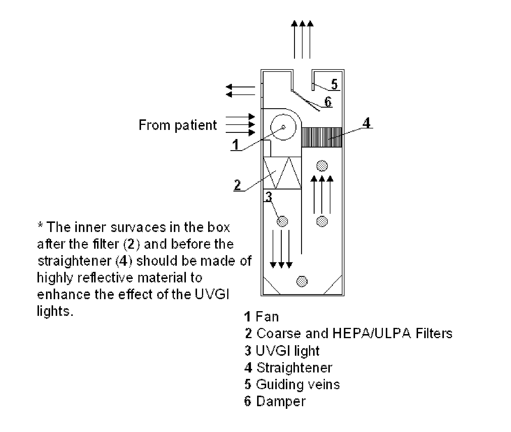
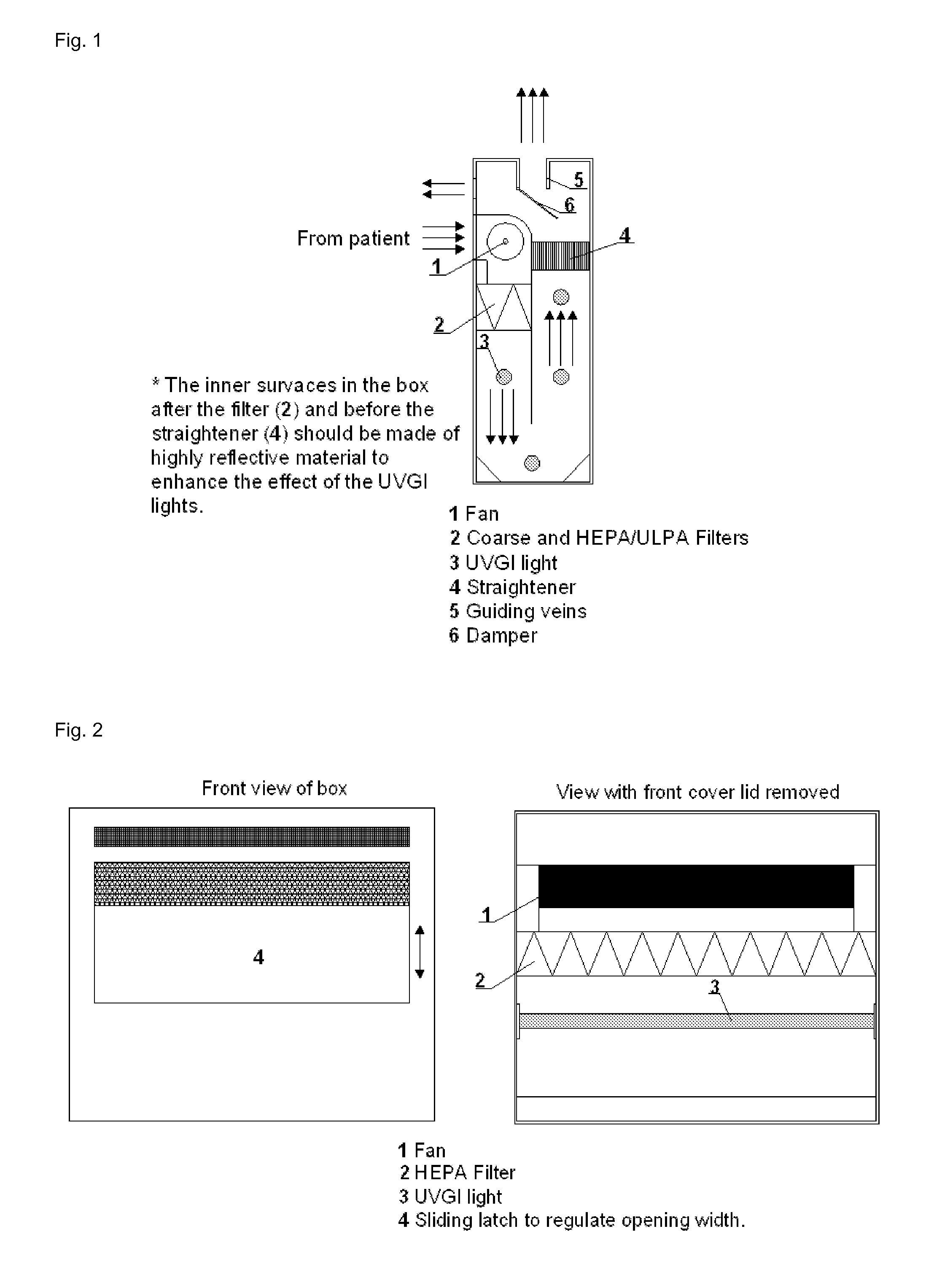
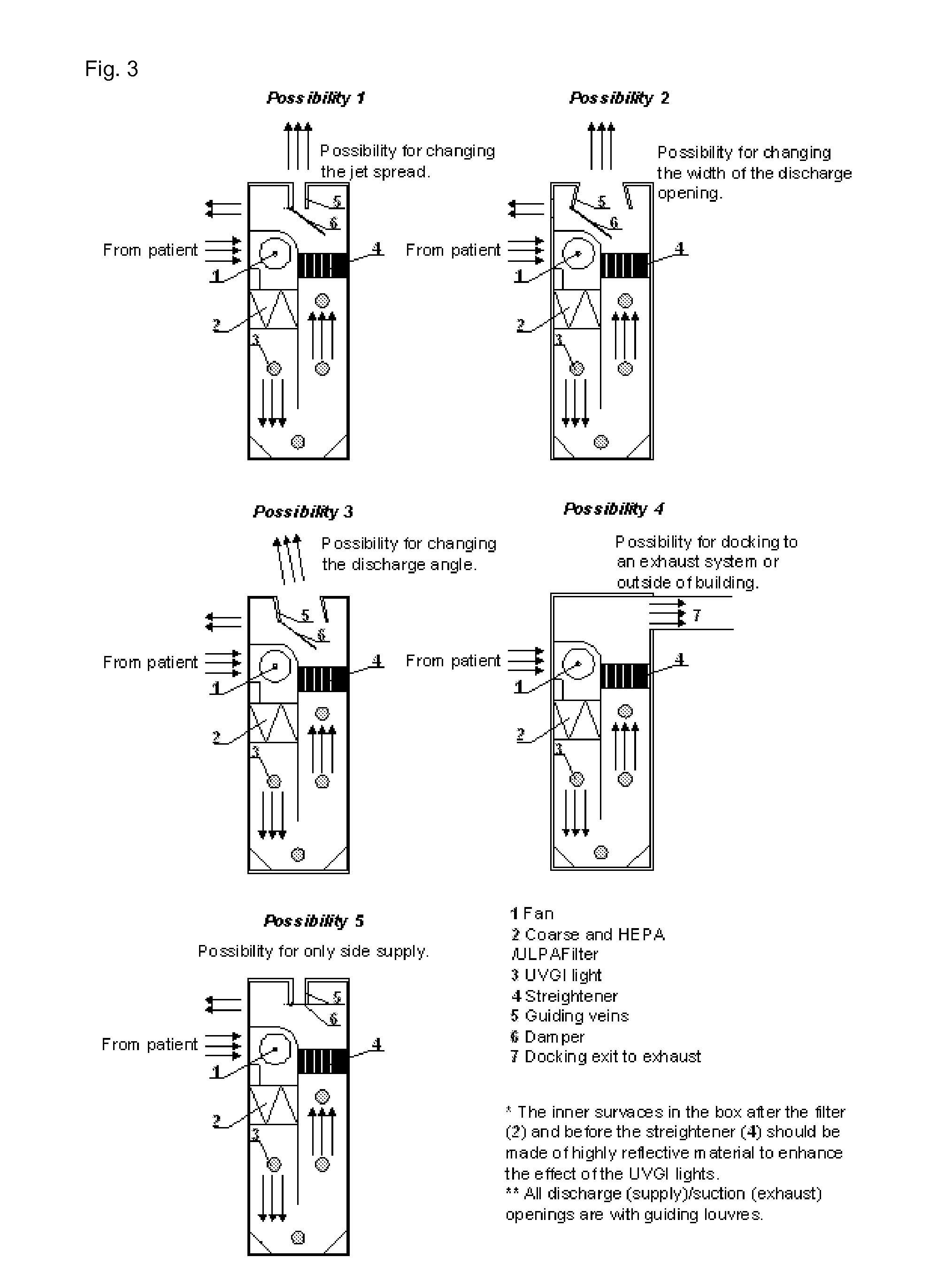
The present invention relates to an air distribution control and filtration / ventilation system for ventilating and cleaning air in a safe and efficient manner. The system includes a cabinet with at least one air slot for directing air in and out of the unit, a fan for circulating air, and a means for killing or inhibiting the growth of microorganisms or viruses present in the air. The system can be portable and designed for use in multiple locations. It can also be used in bed to help prevent the spread of health hazardous airborne matter. The system can provide air with a controlled composition and can be designed to isolate or partly isolate areas from airborne health hazards.

Problems solved by technology

However, the airflow towards the exhaust opening is not effective for removing contaminated air delivered by e.g. a diseased patient 1-4 m from the exhaust opening.
The air movement in the vicinity of exhausts is quite complex.
Generally, the air velocity distribution across an exhaust surface is not uniform and is influenced by wake formation near the sides of the exhaust or flow contraction, which results in reduction of the effective face area of the exhaust.
Nevertheless, medical staff working in infectious isolation units is under elevated risks of getting sick and spreading the disease.
The problem is that with perfect mixing the concentration of pathogens in the room would be the same in the whole occupied space.
It is evident that the recommended high flow rates will imply quite a lot of energy consumption to condition the air in isolation rooms within the recommended range of indoor temperatures of 21-24° C. Also the ducting, fans and HVAC (heating, ventilation and air-conditioning) unit required for the ventilation systems would be expensive and would occupy quite a lot of space.
Another important issue is that this kind of ventilation works with 100% outdoor air, which additionally raises the running costs of the units and make them quite energy inefficient.
Use of HEPA filters themselves could become source of secondary spread of pathogens if not changed on regular bases.
Usually they are situated out of the ventilated area which elevates the risk of contamination and thus infection.
This is another cost related issue for the maintenance of such a system.
The use of UVGI when placed in the ventilated area is not quite efficient because the source generating pathogens is located in the lower height of the ventilated space while the UVGI unit for safety reasons is typically installed far way in the upper zone (not lower than 1.7 m above the floor).
Some of the pulmonary activities, i.e. coughing / sneezing, generate quite strong air movement with initial velocities as high as 30 m / s, that completely destroy the ventilation air pattern in the rooms and enhance the airborne cross-infection risk among occupants.
Prior art products exists which are ventilators that clean the air, however, these ventilators do not produce an air curtain which can be used to partly or fully isolate an individual which is diseased, or which is at risk of obtaining a disease due to the spread of airborne infections.
When handling food products and infectious air gets into contact with the food ingredients, food or beverages a contamination may occur making the product unsalable due to growth of microorganisms, etc. or the product may become unsafe to eat.

Method used


Image

  • Device and method for reducing spread of microorganisms and airborne health hazardous matter and/or for protection from microorganisms and airborne health hazardous matter
  • Device and method for reducing spread of microorganisms and airborne health hazardous matter and/or for protection from microorganisms and airborne health hazardous matter
  • Device and method for reducing spread of microorganisms and airborne health hazardous matter and/or for protection from microorganisms and airborne health hazardous matter

Examples


example 1

[0277]This example describe the results obtained with a setup as illustrated in FIGS. 4a and 4b and the results shown in FIGS. 5 and 6.

[0278]In this example of the invention, a bed integrated filtration / ventilation unit was incorporated within the side head boards of a hospital bed and the filtration / ventilation unit exhausted the air from the pulmonary activities of the patient (breathing, coughing, sneezing etc, cleansed the air from the presence of pathogens and other health-hazardous matter (toxins), then discharged the air vertically through a horizontal slot, and at a high initial velocity towards the ceiling where it was exhausted by the total volume ventilation. The system can be designed to run in conjunction with total volume ventilation as shown in FIG. 4.

[0279]The filtration / ventilation unit of the experiment consisted of two linear units with fans (low energy consumption and low noise level) installed in the side elements of each unit. Exhaled / coughed air from a patient...

example 2

[0284]A set of experiments were performed to prove the effectiveness of the bed incorporated device. The measurements were commenced in a climate chamber that simulated a hospital isolation room with two beds with patients (FIG. 9). Mixing ventilation with one rectangular supply diffuser and 2 rectangular exhaust units installed on the ceiling was used to ventilate the room. The supply air diffuser was positioned in the center of the ceiling, while the 2 exhausts were positioned with one above each bed and above the head of each dummy (patient).

[0285]FIG. 9 shows the set-up during the experiments. Coughing dummy (1) facing the doctor (thermal manikin) (2) and “exposed” dummy (3) on second bed.

[0286]Two scenarios were examined: scenario 1—two patients and a doctor were simulated and scenario 2—only two patients. During the experiments with scenario 1 the doctor was simulated by a thermal manikin with body size and shape as an average Scandinavian woman. The two patients were simulate...

example 3

[0307]A set of experiments were performed to demonstrate the ability of the bed incorporated filtration / ventilation unit to evacuate the exhaled infected air in case of breathing. The set up of the experiment resembled very much the one described in Example 2 (FIG. 9). In this case 2 thermal manikins were used: one to resemble the doctor and a second one to mimic the sick patient spreading the diseases.

[0308]FIG. 9 shows the set-up during the experiments. Coughing dummy (1) changed with breathing thermal manikin facing the doctor (second thermal manikin) (2) and “exposed” dummy (3) on second bed.

[0309]Two scenarios were examined: 1—two patients and a doctor, and 2—only the two patients in the room. During the experiments in scenario 1 (FIG. 10) the doctor (2) was simulated by a thermal manikin with realistic body shape. The infected patient was substituted with a second breathing thermal manikin (1). The second patient was a thermal dummy (3) with a simplified body shape but close t...


PUM

PropertyMeasurementUnit
velocityaaaaaaaaaa
heightaaaaaaaaaa
widthaaaaaaaaaa

Abstract

Disclosed is an air distribution control unit or a filtration / ventilation unit which is portable and / or can be mounted on or integrated in furniture e.g. as a cabinet of at the head region of a bed. The filtration / ventilation unit cleanses air from a person / patient by aspirating the person's / patient's exhalation air into the filtration / ventilation unit. To construct an at least partly isolated area around the patient, filtered air can be directed e.g. vertically out of the filtration / ventilation unit to perform an air curtain. Use of the filtration / ventilation unit reduces the risk of dissipation of air-borne diseases and health hazardous matter, and reduces the amount of air to ventilate a room with patients.

Description

[0001]All patent and non-patent references cited in the present application, are also hereby incorporated by reference in their entirety.FIELD OF INVENTION[0002]The present invention relates to a filtration and ventilation unit, a filtration and ventilation system and a method for ventilating and cleaning the air and minimising the risk of microorganisms, viruses or any other health hazardous airborne matter to dissipate from one person to other persons. The filtration / ventilation unit and filtration / ventilation system is capable of removing and / or filtering output air e.g. exhalation air within short distance from the source (individual) providing the output air. The filtration / ventilation unit and filtration / ventilation system is also capable of producing an air curtain which can partly isolate an area to be cleaned from microorganisms, viruses and / or any other health hazardous airborne matter or an area to be free of microorganisms, viruses and / or any other health hazardous airbo...

Claims


Application Information

Patent Timeline
Patent Type & Authority Applications(United States)
IPC IPC(8): F24F3/16B01D46/42F24F6/00B01D53/26F24F9/00F24F7/06
CPCA61G10/02A61G13/108A61G15/10A61G2203/46A61L9/20A61L2209/111A61L2209/14F24F3/1607F24F3/163G16H50/80
Inventor MELIKOV, ARSEN KRIKORZHU, SHENGWEIBOLASHIKOV, ZHECHO DIMITROV
Owner DANMARKS TEKNISKE UNIV
Why Eureka
Eureka Blog
Learn More