Eureka AIR delivers breakthrough ideas for toughest innovation challenges, trusted by R&D personnel around the world.

Washing machine and control panel assembly thereof

a technology of control panel and wash machine, which is applied in the direction of contact mechanism, protective switch operating/release mechanism, other washing machines, etc., can solve the problems of rotary knob , inability to smoothly rotate, and provide an unpleasant feeling to the user, so as to minimize the shaking of the rotary knob

Active Publication Date: 2008-11-27
SAMSUNG ELECTRONICS CO LTD
View PDF1 Cites 69 Cited by
  • Summary
  • Abstract
  • Description
  • Claims
  • Application Information

AI Technical Summary

Benefits of technology

[0009]Therefore, one aspect of the embodiment is to provide a washing machine, which minimizes a shaking of a rotary knob, and a control panel assembly thereof.
[0010]Another aspect of the embodiment is to provide a washing machine, which minimizes problems caused by an interference of a rotary knob with other surrounding parts, and a control panel assembly thereof.
[0024]The angled extension may abut the boss at an abutting point and angle away from the boss from the abutting point to increase a diameter of a boss insertion hole formed between the angled extension and the boss.
[0029]The angled extension may abut the boss at an abutting point and angle away from the boss from the abutting point to increase a diameter of a boss insertion hole formed between the angled extension and the boss.

Problems solved by technology

In such a control panel assembly, when a user manipulates the rotary knob 6, the rotary knob 6 shakes and thus provides an unpleasant feeling to the user.
However, in this case, when the rotary knob 6 is manipulated, the rotary knob 6 interferes with the decoration window 5 and thus cannot be smoothly rotated, or the rotary knob 6 provides an unpleasant feeling to the user.
Further, noise due to friction occurs.

Method used


Image

  • Washing machine and control panel assembly thereof
  • Washing machine and control panel assembly thereof
  • Washing machine and control panel assembly thereof

Examples


Embodiment Construction

[0036]Reference will now be made in detail to the embodiment, an example of which is illustrated in the accompanying drawings, wherein like reference numerals refer to like elements throughout. The embodiment is described below to explain the present invention by referring to the annexed drawings.

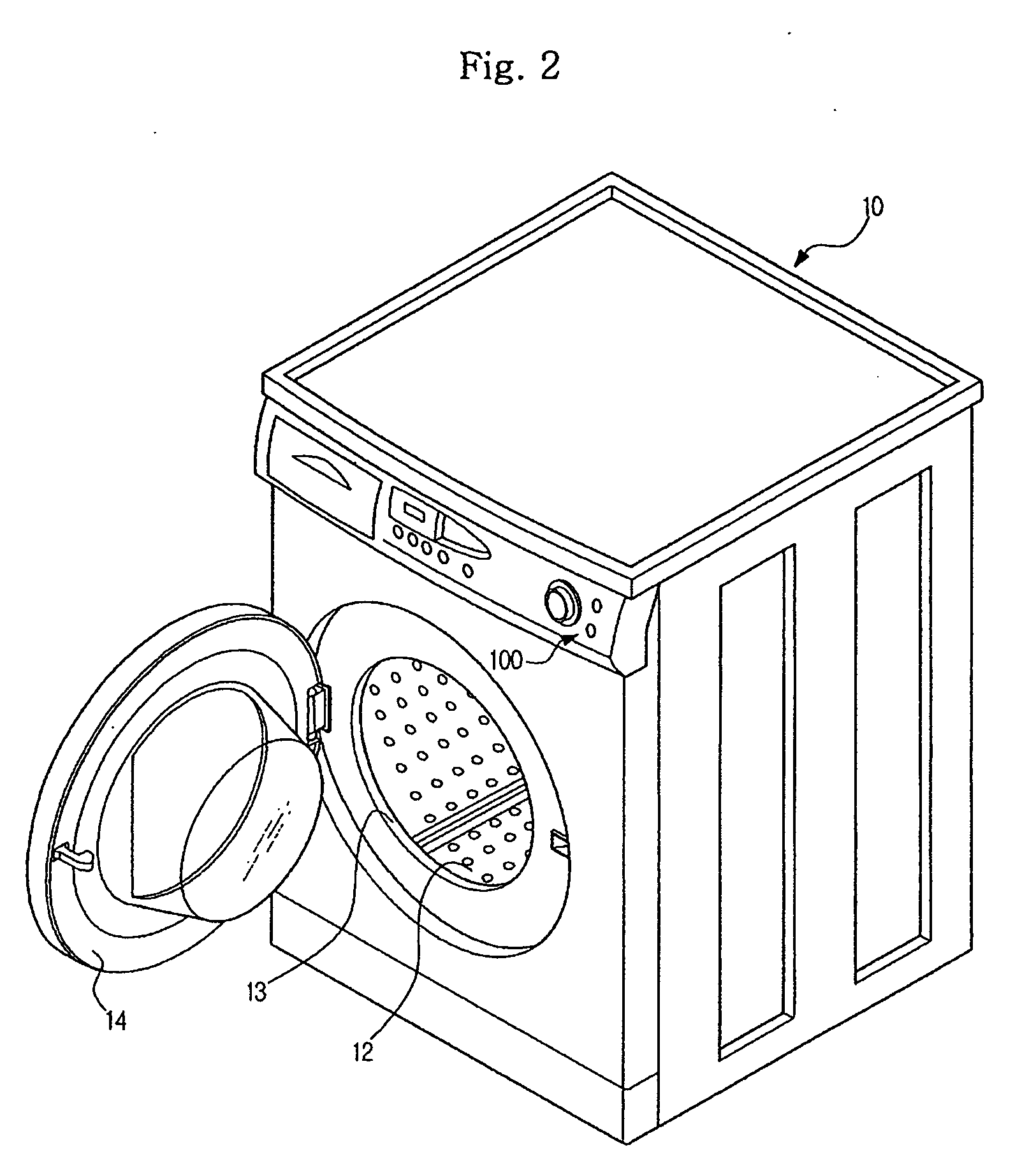
[0037]FIG. 2 is a perspective view of a washing machine in accordance with the present embodiment.

[0038]As shown in FIG. 2, the washing machine in accordance with the present embodiment includes a main body 10 forming an external appearance of the washing machine, a tub (not shown) installed in the main body 10 to store washing water, and a drum 12 rotatably installed in the tub to wash laundry. An opening 13 is formed through a front surface of the main body 10 so that a user can put laundry into an inside of the tub through the opening 13, and a door 14 to open and close the opening 13 is installed. A control panel assembly 100 to control an operation of the washing machine is provided on...


PUM


Abstract

Disclosed is a washing machine, a control panel assembly of which has an improved structure to minimize problems caused by a shaking of a rotary knob and the interference of the rotary knob with other surrounding parts. The control panel assembly of the washing machine includes a control panel; a knob guide installed on the control panel; and a rotary knob rotatably mounted on the knob guide and including a boss passing through the knob guide. The knob guide includes a boss insertion part restricting the boss to prevent the rotary knob from shaking. The boss insertion part includes an extension extended from the bottom surface of the knob guide and forming a boss insertion hole, into which the boss is inserted, therein.

Description

CROSS-REFERENCE TO RELATED APPLICATIONS[0001]This application claims the benefit of Korean Patent Application No. 2007-0050632, filed May 25, 2007, in the Korean Intellectual Property Office, the disclosure of which is incorporated herein by reference.BACKGROUND[0002]1. Field[0003]The present invention relates to a washing machine, and more particularly, to a washing machine, a control panel assembly which has an improved structure to minimize problems caused by a shaking of a rotary knob and an interference of the rotary knob with other surrounding parts.[0004]2. Description of the Related Art[0005]Washing machines are apparatuses that wash clothes using electric power. In general, a washing machine includes a tub storing washing water, and a drum rotatably installed in the tub. When the drum is rotated or a pulsator installed in the drum is rotated under the condition that laundry and washing water containing a detergent are put into the drum, the laundry rubs against the drum and...

Claims


Application Information

Patent Timeline
IPC IPC(8): H01H19/14
CPCD06F39/005H01H19/025H01H19/02D06F34/30D06F2101/14D06F2105/58D06F37/26D06F39/12D06F34/28H01H71/56H01H25/008H01H2219/002H01H2219/028H01H2219/036H01H2221/01H01H2221/062
Inventor KIM, JIN DOOSEO, JEONG KI
Owner SAMSUNG ELECTRONICS CO LTD
Why Eureka
Eureka Blog
Learn More