
Mechanical oscillator

a mechanical oscillator and oscillator technology, applied in the field of mechanical oscillator devices, can solve the problems of more sophisticated devices that require expensive digital hardware, poor time response and noise susceptibility of negative-feedback type controllers, and relatively limited fundamental advances in the design of mechanical oscillator systems, so as to improve the control of primary stationary vibrations and small propagating vibration components.

Inactive Publication Date: 2012-05-31
GREGG JOHN FRANCIS +1
View PDF4 Cites 23 Cited by
  • Summary
  • Abstract
  • Description
  • Claims
  • Application Information

AI Technical Summary

Benefits of technology

[0005]Such a stabilized positive feedback arrangement is self exciting at the effective resonance frequency of the mechanical structure and avoids the need for an external fixed or variable frequency driver. Moreover, by providing an adjustable transmission path length in the mechanical structure (for example by mounting the actuator and / or sensor for movement relative to one another), and / or by providing within the controller or another signal processing element which forms part of the oscillator control loop a means for varying an electronic frequency dependent transfer function via a frequency dependent gain element, the arrangement is capable of establishing (and desirably operates with) both stationary (standing) and travelling (propagating) mechanical vibrations. Certain preferred embodiments of this invention operating in conjunction with distributed-parameter mechanical systems, employ substantially stationary mechanical vibrations with a small propagating vibration component also present.
[0006]In these certain embodiments, employing a controllable propagating vibration component provides for improved control of the primary stationary vibrations. In particular, most distributed-parameter mechanical structures (that is mechanical structures with a characteristic dimension comparable to the wavelength of a mechanical vibration) do not have a single mechanical resonance frequency but instead, a family of vibrational modes. Embodiments of the present invention enable a particular one of these modes to be selected and locked on to provided that the sensor and actuator are correctly located and the electronic frequency dependent transfer function is appropriately designed.

Problems solved by technology

Despite the considerable technological progress of the last three decades, fundamental advances in the design of mechanical oscillator systems have been relatively limited: negative-feedback controllers of the type developed in the late 1970s—see for example U.S. Pat. No. 4,177,434—and quasi-positive feedback control-loop oscillators remain the prevalent technologies.
Although adequate in many contexts, these arrangements have certain fundamental limitations which present significant technological obstacles in the most demanding applications.
Negative-feedback type controllers are plagued by poor time responses and noise susceptibility, particularly in applications where it is a requirement that a shifting, sharp (i.e. high quality factor) mechanical resonance is tracked in real-time.
Control-loop oscillators have similar drawbacks; the more sophisticated devices also require expensive, specialist digital hardware.

Method used


Image

  • Mechanical oscillator
  • Mechanical oscillator
  • Mechanical oscillator

Examples


Embodiment Construction

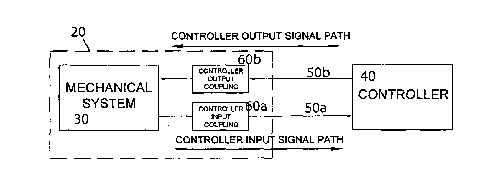
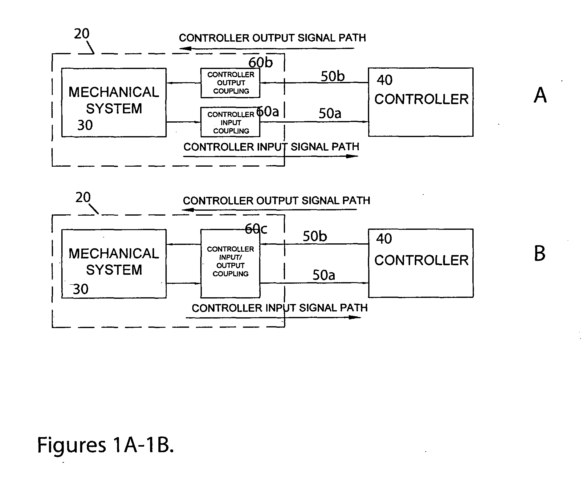
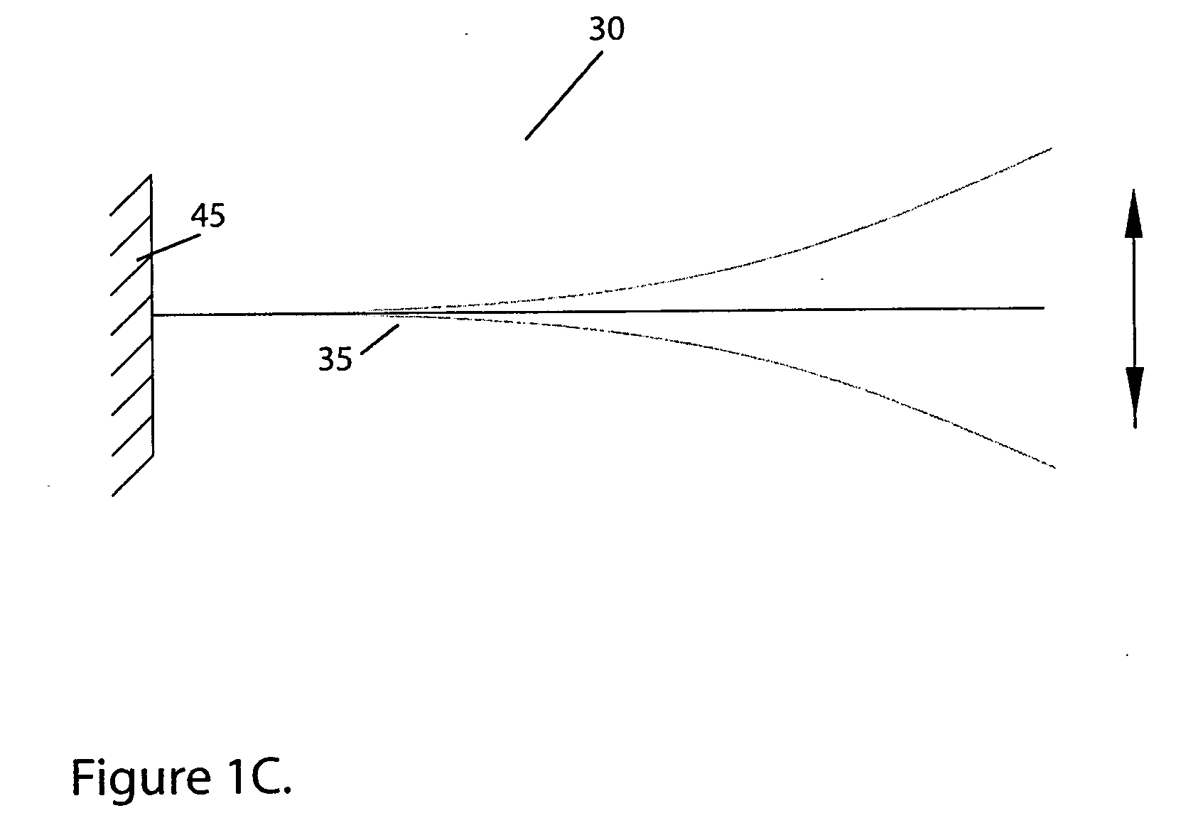
[0047]FIGS. 1A and 1B show, at a most general level, the structure of a mechanical oscillator device 10 embodying the present invention. In each case, the mechanical oscillator device comprises a mechanical structure 20 which includes a mechanical system 30, connected to a controller 40. The mechanical system 30 is the functional part or active region of the mechanical structure 20, which lends functionality to a particular implementation of the mechanical oscillator device 10. Its exact-nature depends on the desired functionality of that mechanical oscillator device, but it may be a one, two or three-dimensional mechanical element with one or more resonant mode(s), that is, a mechanical element which responds preferentially at one or more frequencies, for example, a macro, micro or nano-mechanical beam, cantilever, ring or membrane. FIG. 1C illustrates a simple schematic example of a typical mechanical system 30: a cantilever 35 which is singly clamped to a support 45 and which may...


PUM


Abstract

A mechanical oscillator arrangement includes a mechanical structure (30) having at least one transmission path through it, and at least one mode. A controller (40) is provided with an amplifier (70) and a feedback network (80, 90) which together provide a positive feedback oscillator for exciting a mode of the mechanical structure (30). The feedback network (80, 90) comprises a non linear amplitude control element (N-LACE) (90), a frequency dependent gain element with an electronic transfer function, and a phase compensator (80). The mechanical oscillator arrangement also includes an actuator (606) which excites the mechanical structure (30) based upon an output from the controller (40), and a sensor (60a) which senses vibrations in the mechanical structure (30) and then outputs a signal to the controller (40) based upon the sensed vibrations. Such a stabilized positive feedback arrangement is self exciting at the effective resonance frequency of the mechanical structure and avoids the need for an external fixed or variable frequency driver.

Description

FIELD OF THE INVENTION[0001]This invention relates to a mechanical oscillator device.BACKGROUND OF THE INVENTION[0002]Mechanical resonances have been exploited for many decades in applications ranging from music-making to industrial demolition. Relatively recently, renewed interest in mechanical oscillators—instruments designed specifically for the excitation and maintenance of mechanical resonances—has been catalysed by the emergence of new applications in micro and nanoscale mechanical automation, information processing, and certain types of scanning microscopy and spectroscopy.[0003]Despite the considerable technological progress of the last three decades, fundamental advances in the design of mechanical oscillator systems have been relatively limited: negative-feedback controllers of the type developed in the late 1970s—see for example U.S. Pat. No. 4,177,434—and quasi-positive feedback control-loop oscillators remain the prevalent technologies. Although adequate in many context...

Claims


Application Information

Patent Timeline
Patent Type & Authority Applications(United States)
IPC IPC(8): H03B5/36
CPCB82Y35/00G01N3/32G01N2203/0008H03K17/95G01N2203/0688G01Q60/52G01N2203/0051
Inventor GREGG, JOHN FRANCISKARENOWSKA, ALEXY DAVISON
Owner GREGG JOHN FRANCIS
Learn More