System for rapid assessment of grade variations and method for using a system

a technology of grade variation and system, applied in the field of systems, can solve the problems of inability to fully appreciate the expertise needed for proper landscape construction, inability to use traditional survey equipment for estimating or calculating grade variation, and inability to meet the functional-concept plan phase of landscape construction projects. to achieve the effect of minimizing the impact on job-site operations

Inactive Publication Date: 2012-05-17
HOLGATE MICHAEL S
View PDF9 Cites 4 Cited by
  • Summary
  • Abstract
  • Description
  • Claims
  • Application Information

AI Technical Summary

Benefits of technology

[0004]The present invention provides a system for estimating or calculating grade variations that is convenient to use and that provides data of sufficient precision for the estimating or calculating process and a method for using such a system. The inventive system for estimating or calculating grade variations can be deployed for estimating or calculating grade variations in connection with the placement and installation of fences, gates, pools, drainage, steps, decks, patios, contour features, ponds, driveways, and other site improvements. In addition to a deployment of the system to quickly establish and / or verify elevations of outdoor features, the inventive system for estimating or calculating grade variations can be deployed to quickly establish and / or verify elevations in a building structure for installing cabinets, countertops, alternating current outlets, etc.
[0010]In accordance with the present invention, at least one possible configuration of the system can be advantageously manufactured at a comparatively low cost. Also, the system may provide for interchanging existing components to meet consumer budget / demands (such as, for instance, using scrap pipe with integrated-mount / leveling-instrument, or using commercially available leveling-instruments with a generic threaded mount system). Advantageously, the system does not require typical eight-foot (8′) pole lengths and / or an expanding design to accommodate interior static setup as can be required, in contrast, in connection with several conventional approaches for estimating grade variations. Also, the system does not require a calibrated target as can be required, in contrast, in connection with traditional tripod / survey methods.
[0012]While tripods, floor-to-ceiling poles, and other level mounting combinations or equipment may be complex to setup, the system of the present invention can be configured to minimize such complexity via, for example, configuring the system to be operable without limitations imposed by the location of use, ensuring that no procedural leveling tasks such as turning knobs are necessary, and minimizing or eliminating extra steps to establish post rigidity. The level of expertise necessary to operate the system is greatly reduced compared to traditional, complicated leveling instruments with multiple components that must be considered independently and function harmoniously.
[0014]Typical set up tasks involved with tripods, floor-to-ceiling poles, and other level mounting combinations / equipment can include an initial setup for the support and / or mounting of the equipment, followed by setup of the leveling-instrument at each new position / location. In contrast, the system of the present invention provides, in one configuration, a simple hand-to-pole fulcrum alignment technique using limited pole motion (from ground pivot point) to advantageously properly orient a leveling-instrument. The system can also offer rotational freedom to align with various pole marks that define different measuring units.
[0015]The inspections performed by supervisors, homeowners, designers, engineers, and other parties may interfere with job-site resources such as personnel and / or equipment. Moreover, upon the arrival of these parties conducting such inspections, ongoing work must be delayed or is otherwise interrupted as survey equipment is commandeered. One configuration of the system of the present invention offers a new combination of speed, accuracy, and mobility to establish and / or verify construction elevations while minimizing the impact on job-site operations. This system may also be used in concert with more permanent instruments to determine ideal locations for complex setups.

Problems solved by technology

The expertise needed for proper landscape construction is often not fully appreciated when it comes to developing or improving the ground property of a house or building site.
A landscape designer, engineer, technician, or architect generally approaches each project armed with a pencil, a writing pad and a tape measure but there is no standard or frequently used device for estimating or calculating grade variations that is convenient to use and that provides data of sufficient precision for the estimating or calculating process.
The lack of such a device is all too evident when an installation is in progress on a house or building site and problems that could have been addressed in a prior planning step are first noticed and corrected (or attempted to be corrected) by field crews.
While laser-assisted measuring devices are thus known, and have been extensively integrated into survey equipment that is deployed for landscape construction uses, the use of traditional survey equipment for estimating or calculating grade variations is in the end not practical for the functional-concept plan phase of a landscape construction project.
The need for a two person crew—with one person operating the laser device and another person operating a complementary deflector associated with the laser device—imposes a manpower requirement and reduces the convenience of such traditional survey devices.
A further drawback with traditional survey equipment such as conventional tripods, floor-to-ceiling poles, and other level mounting combinations and equipment is the complexity involved in interpreting the data generated by such equipment, including the need to perform mathematical calculations to yield results.

Method used


Image

  • System for rapid assessment of grade variations and method for using a system
  • System for rapid assessment of grade variations and method for using a system
  • System for rapid assessment of grade variations and method for using a system

Examples


Embodiment Construction

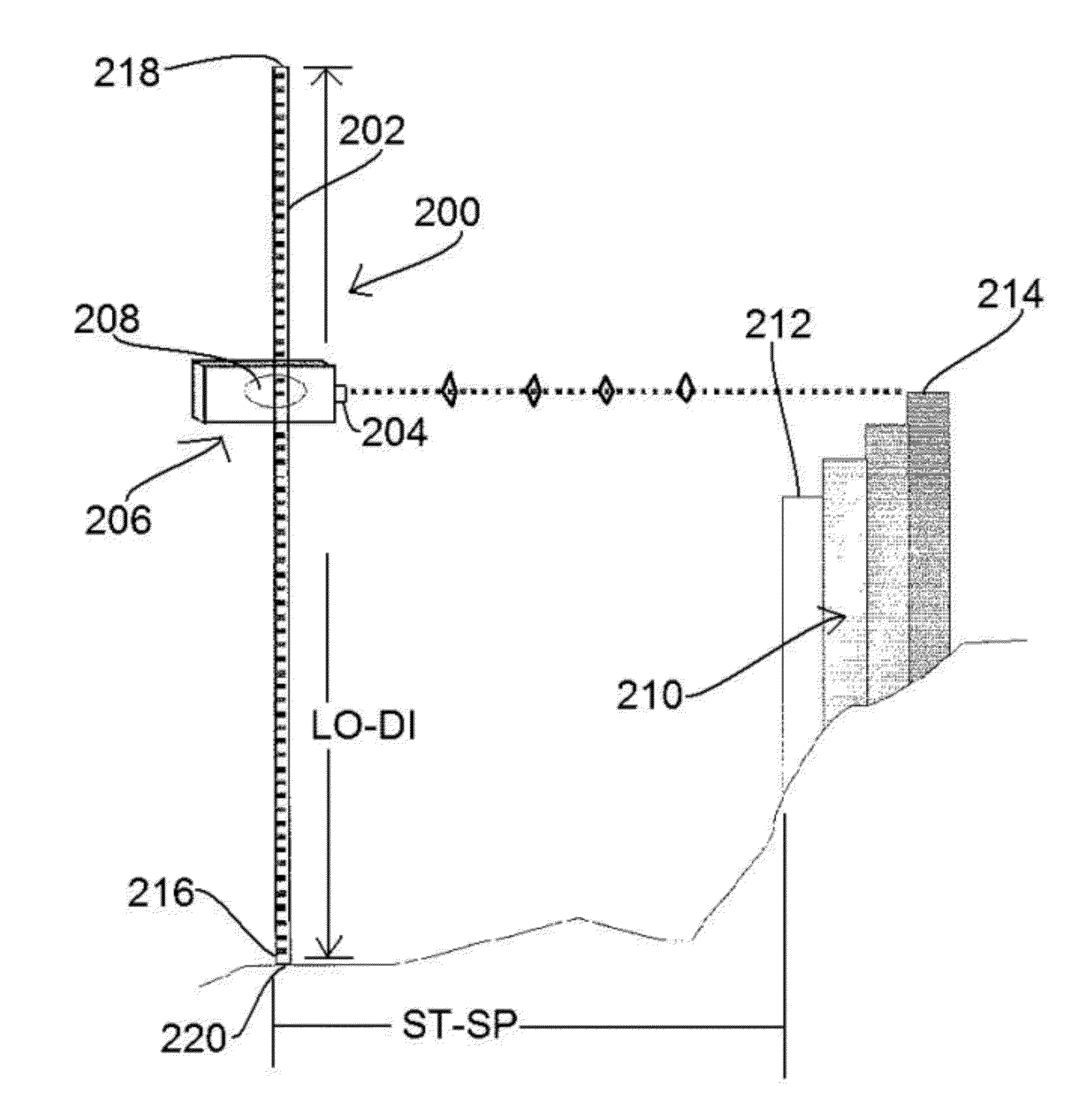
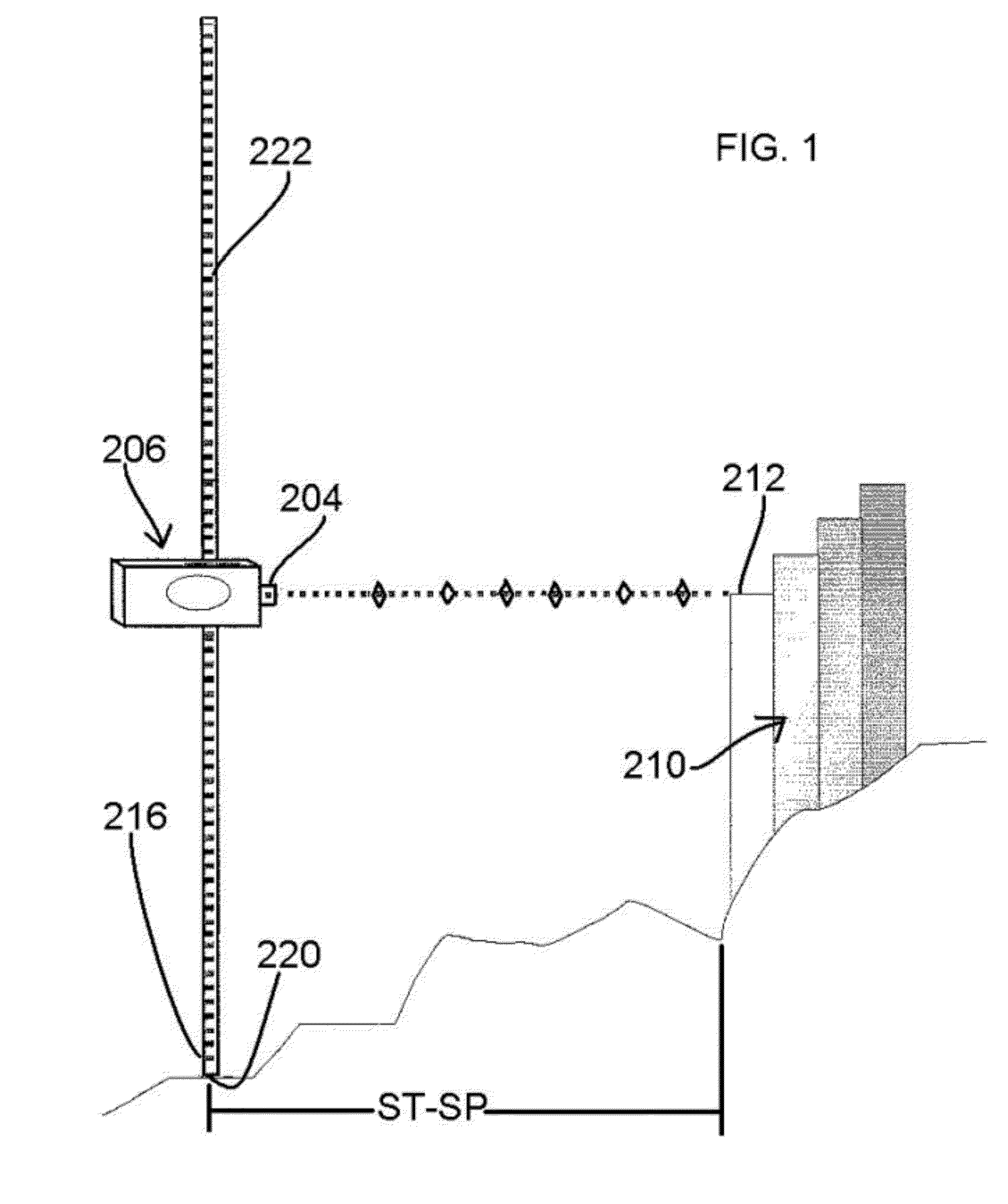
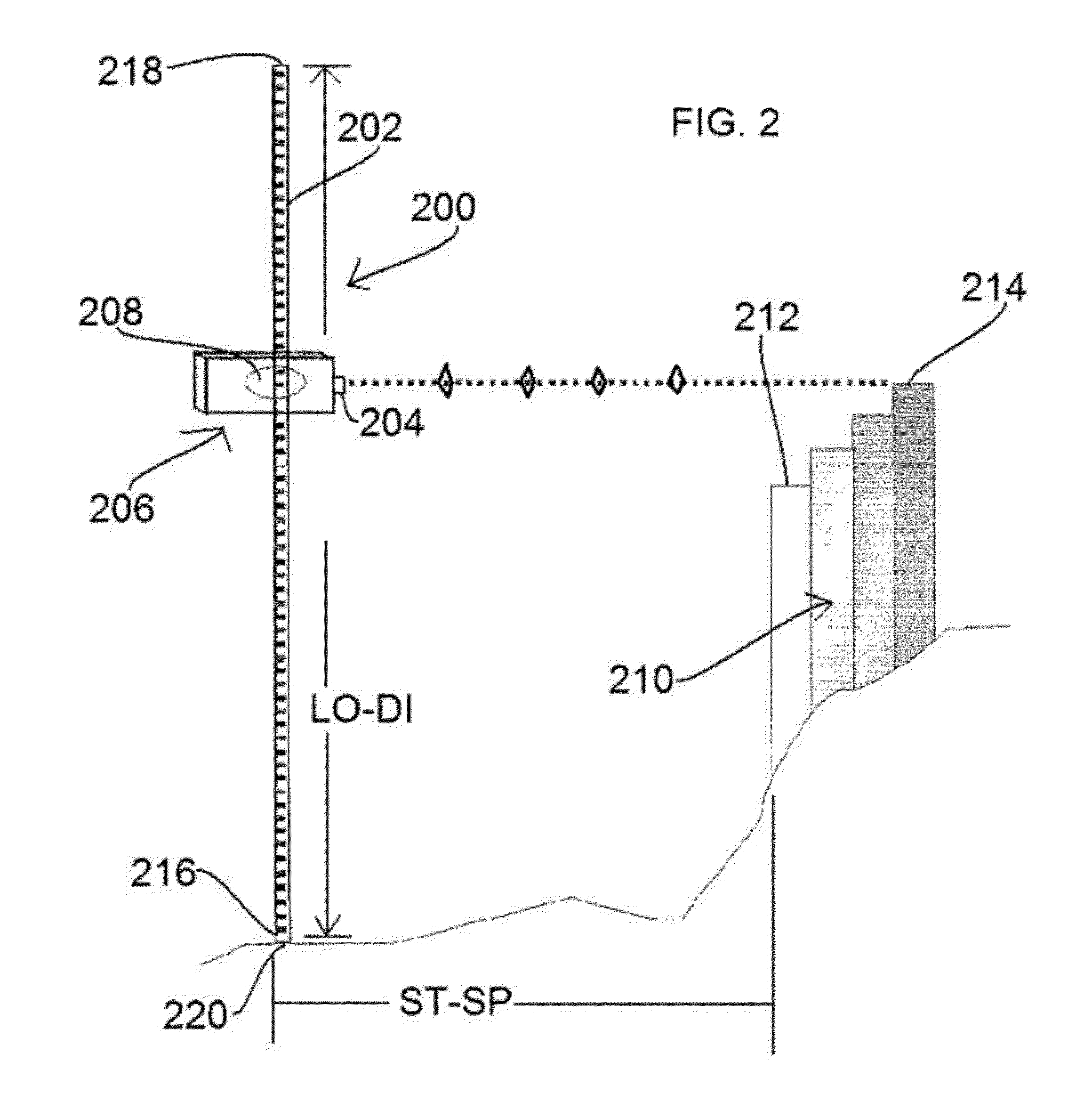
[0028]The present invention provides a system that provides information to assess a profile characteristic of a surface. Particular details of a kit version of the system of the present invention will be provided herein but, initially, an overview of the inventive system will be provided with reference to FIGS. 1 and 2, wherein a core system is illustrated. As seen in FIG. 1, which is a side elevational schematic view of the core system of the present invention, the core system, hereinafter designated as the core system 200, comprises a reference component in the form of a pole 202, a first target kickoff device in the form of a scope 204, a follow-on positioner in the form of a movable bracket 206, a data interplay device in the form of a chip 208, and other components that will be described hereinafter. The core system 200 is operable to provide information to assess a profile characteristic of a surface such as, as exemplarily illustrated in FIG. 1, a surface formed by a pluralit...


PUM


Abstract

A system for estimating or calculating grade variations of a ground surface is provided that is convenient to use and provides data of sufficient precision for the estimating or calculating process. The system can be deployed for estimating or calculating grade variations in connection with the placement and installation of fences, gates, pools, drainage, steps, decks, patios, contour features, ponds, driveways, and other site improvements. In addition to a deployment of the system to quickly establish and / or verify elevations of outdoor features, the system can be deployed to quickly establish and / or verify elevations in a building structure for installing cabinets, countertops, or alternating current outlets.

Description

BACKGROUND OF THE INVENTION[0001]The present invention relates to a system for providing information to assess a profile characteristic of a surface and method for using such a system and, more particularly, relates to a system for estimating or calculating grade variations that is convenient to use and that provides data of sufficient precision for the estimating or calculating process and a method for using such a system.[0002]The expertise needed for proper landscape construction is often not fully appreciated when it comes to developing or improving the ground property of a house or building site. A landscape designer, engineer, technician, or architect generally approaches each project armed with a pencil, a writing pad and a tape measure but there is no standard or frequently used device for estimating or calculating grade variations that is convenient to use and that provides data of sufficient precision for the estimating or calculating process. The lack of such a device is ...

Claims


Application Information

Patent Timeline
IPC IPC(8): G06F15/00G01B11/24
CPCG01C15/002G01C5/00
Inventor HOLGATE, MICHAEL S.
Owner HOLGATE MICHAEL S
Why Eureka
Try Eureka