Piezoelectric element, liquid ejecting head, and liquid ejecting apparatus

a liquid ejecting head and electric element technology, applied in piezoelectric/electrostrictive/magnetostrictive devices, device material selection, device material selection, etc., can solve problems such as similar present cracks are liable to occur or grow, etc., to achieve excellent reliability, reduce environmental load, suppress the effect of crack occurrence or growth

Inactive Publication Date: 2012-05-17
SEIKO EPSON CORP
View PDF2 Cites 0 Cited by
  • Summary
  • Abstract
  • Description
  • Claims
  • Application Information

AI Technical Summary

Benefits of technology

[0015]A second aspect of the invention is a liquid ejecting apparatus equipped with the liquid ejecting head of the first aspect. In this aspect, the liquid ejecting apparatus has the piezoelectric layers in which the occurrence or growth of cracks is suppressed, and therefore the liquid ejecting apparatus is excellent in terms of reliability.
[0016]In addition, a third aspect of the invention is a piezoelectric element equipped with a piezoelectric layer and electrodes provided in the piezoelectric layer, in which the piezoelectric layer is a complex oxide having a perovskite structure that includes Bi, Fe, Ba, Ti, and Co, and a Co / (Co+Fe) ratio, which is the mole ratio of Co to the total amount of Co and Fe, of 0.02 to 0.07. According to this, the occurrence or growth of cracks can be suppressed in the piezoelectric layer by using the piezoelectric material composed of the complex oxide having the perovskite structure that includes Bi, Fe, Ba, Ti, and a predetermined amount of Co as the piezoelectric layer. In addition, since the content of lead is suppressed, the environmental load can be reduced.

Problems solved by technology

The piezoelectric layer composed of such a piezoelectric material has a problem in that cracks are liable to occur and grow therein.
Particularly, cracks become liable to occur or grow as time passes after the piezoelectric layer is manufactured.
Of course, such a problem is similarly present even in other liquid ejecting heads that discharge liquid droplets other than ink as well as the ink jet-type recording head that discharges ink.

Method used


Image

  • Piezoelectric element, liquid ejecting head, and liquid ejecting apparatus
  • Piezoelectric element, liquid ejecting head, and liquid ejecting apparatus
  • Piezoelectric element, liquid ejecting head, and liquid ejecting apparatus

Examples


first embodiment

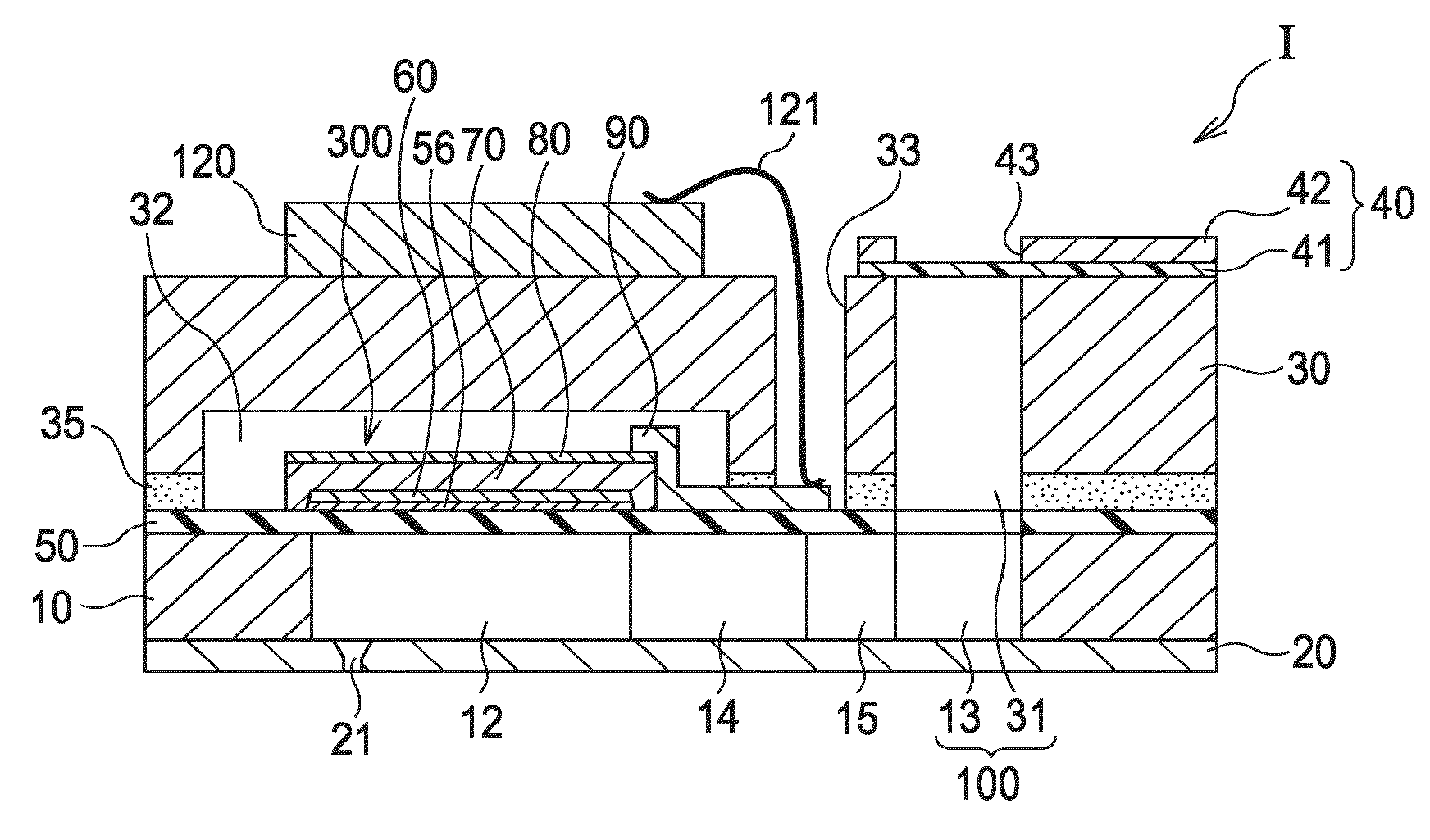
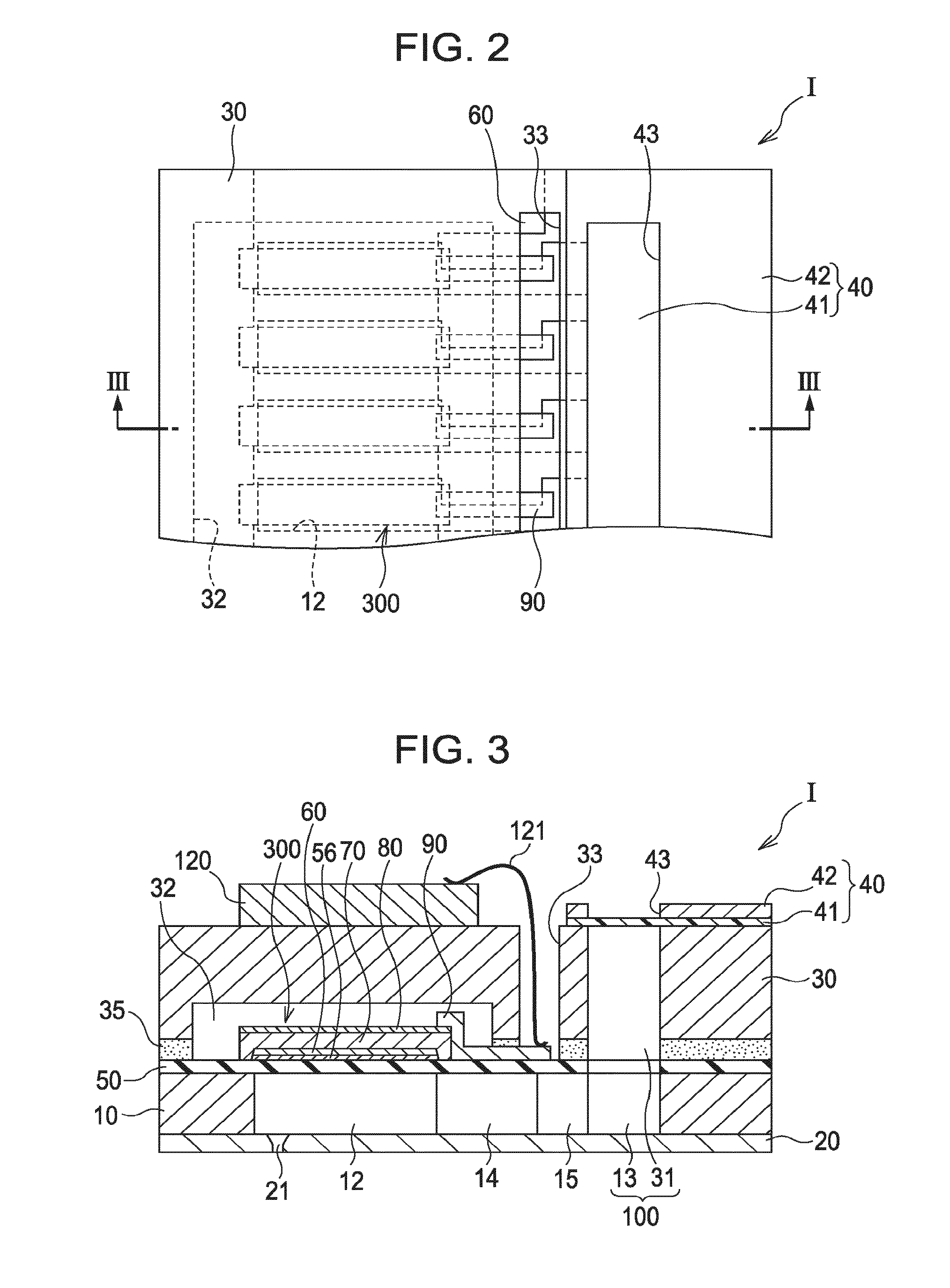
[0043]FIG. 1 is an exploded perspective view showing the schematic configuration of an ink jet-type recording head which is an example of the liquid ejecting head according to the first embodiment of the invention, FIG. 2 is a plan view of FIG. 1, and FIG. 3 is a cross-sectional view taken along the III-III in FIG. 2. As shown in FIGS. 1 to 3, a flow channel-forming substrate 10 of the present embodiment is made of a silicon single crystal substrate and has an elastic film 50 made of silicon dioxide formed on one surface.

[0044]A plurality of pressure-generating chambers 12 are provided in parallel in the width direction in the flow channel-forming substrate 10. In addition, a communicating portion 13 is formed in an area outside the longitudinal direction of the pressure-generating chambers 12 in the flow channel-forming substrate 10, and the communicating portion 13 and each of the pressure-generating chambers 12 are communicated with each other via an ink supply channel 14 and a c...

example 1

[0082]Firstly, a 1200 nm-thick silicon dioxide film was formed on the surface of a (110)-oriented single crystal silicon substrate by thermal oxidation. Next, a 40 nm-thick titanium film was formed on the silicon dioxide film by the RF magnetron sputtering method, and thermally oxidized, thereby forming a titanium oxide film. Next, a 130 nm-thick platinum film was formed on the titanium oxide film by the RF magnetron sputtering method, thereby manufacturing a (111)-oriented first electrode 60.

[0083]Next, the piezoelectric layer 70 was formed on the first electrode 60 by the spin coating method. The method was as follows. Firstly, an octane solution of bismuth 2-ethylhexanoate, a xylene solution of iron 2-ethylhexanoate, an octane solution of barium 2-ethylhexanoate, an octane solution of titanium 2-ethylhexanoate, and an octane solution of cobalt 2-ethylhexanoate were mixed in a predetermined ratio, thereby preparing a precursor solution. In addition, the precursor solution was drop...


PUM

PropertyMeasurementUnit
mole ratioaaaaaaaaaa

Abstract

A piezoelectric element comprises a piezoelectric layer and electrodes provided to the piezoelectric layer. The piezoelectric layer has a perovskite structure that includes Bi, Fe, Ba, Ti, and Co, and the mole ratio of Co to the total amount of Co and Fe is 0.02 or more and 0.07 or less.

Description

CROSS-REFERENCE TO RELATED APPLICATIONS[0001]The entire disclosure of Japanese Patent Application No. 2010-256347, filed Nov. 16, 2010 and Japanese Patent Application No. 2011-213542, filed Sep. 28, 2011 are expressly incorporated by reference.BACKGROUND[0002]1. Technical Field[0003]The present invention relates to a liquid ejecting head which alters the pressure in pressure-generating chambers communicated to nozzle openings and is equipped with piezoelectric elements having piezoelectric layers and electrodes that apply voltages to the piezoelectric layers, a liquid ejecting apparatus, a piezoelectric element, and a piezoelectric material.[0004]2. Related Art[0005]There is a piezoelectric element configured to pinch a piezoelectric material exhibiting an electromechanical transduction function, for example, a piezoelectric layer (piezoelectric film) composed of a crystallized dielectric material, between two electrodes. Such a piezoelectric element is mounted in, for example, a li...

Claims


Application Information

Patent Timeline
Patent Type & Authority Applications(United States)
IPC IPC(8): B41J2/045H01L41/18
CPCB41J2/14233B41J2002/14241B41J2002/14419H01L41/318H01L41/0973H01L41/1878B41J2202/03H10N30/2047H10N30/8561H10N30/078
Inventor TAKAHASHI, TOSHIAKISAKAI, TOMOHIRO
Owner SEIKO EPSON CORP
Why Eureka
Try Eureka