
Systems and Methods for Removing Heavy Hydrocarbons and Acid Gases From a Hydrocarbon Gas Stream

a technology of acid gas and hydrocarbon gas, which is applied in the direction of separation process, liquefaction, lighting and heating apparatus, etc., can solve the problems of undesirable additional elemental sulfur production, gas separation process creates an issue as to the disposal of separated contaminants, and the practice of venting cosub>2 is sometimes undesirabl

Inactive Publication Date: 2012-04-05
NORTHROP PAUL SCOTT +4
View PDF18 Cites 75 Cited by
  • Summary
  • Abstract
  • Description
  • Claims
  • Application Information

AI Technical Summary

Benefits of technology

[0024]The at least one solid adsorbent bed may be an adsorptive kinetic separations bed. Alternatively, the at least one solid adsorbent bed may comprise at least three adsorbent beds wherein (i) a first of the at least three adsorbent beds is in service for adsorbing heavy hydrocarbon components; (ii) a second of the at

Problems solved by technology

The gas separation process creates an issue as to the disposal of the separated contaminants.
However, in some areas (such as the Caspian Sea region), additional elemental sulfur production is undesirable because there is a limited market.
However, the practice of venting CO2 is sometimes undesirable.
However, for “highly sour” streams, that is, production streams containing greater than about 15% or 20% CO2 and / or H2S, it can be particularly challenging to design, construct, and operate a facility that can economically separate contaminants from the desired hydrocarbons.
The formation of CO2 as a solid disrupts the cryogenic distillation process.

Method used


Image

  • Systems and Methods for Removing Heavy Hydrocarbons and Acid Gases From a Hydrocarbon Gas Stream
  • Systems and Methods for Removing Heavy Hydrocarbons and Acid Gases From a Hydrocarbon Gas Stream
  • Systems and Methods for Removing Heavy Hydrocarbons and Acid Gases From a Hydrocarbon Gas Stream

Examples


Embodiment Construction

Definitions

[0052]As used herein, the term “hydrocarbon” refers to an organic compound that includes primarily, if not exclusively, the elements hydrogen and carbon. Hydrocarbons generally fall into two classes: aliphatic, or straight chain hydrocarbons, and cyclic, or closed ring hydrocarbons, including cyclic terpenes. Examples of hydrocarbon-containing materials include any form of natural gas, oil, coal, and bitumen that can be used as a fuel or upgraded into a fuel.

[0053]As used herein, the term “hydrocarbon fluids” refers to a hydrocarbon or mixtures of hydrocarbons that are gases or liquids. For example, hydrocarbon fluids may include a hydrocarbon or mixtures of hydrocarbons that are gases or liquids at formation conditions, at processing conditions or at ambient conditions (15° C. and 1 atm pressure). Hydrocarbon fluids may include, for example, oil, natural gas, coal bed methane, shale oil, pyrolysis oil, pyrolysis gas, a pyrolysis product of coal, and other hydrocarbons th...


PUM

PropertyMeasurementUnit
Substance countaaaaaaaaaa
Pressureaaaaaaaaaa
Compositionaaaaaaaaaa

Abstract

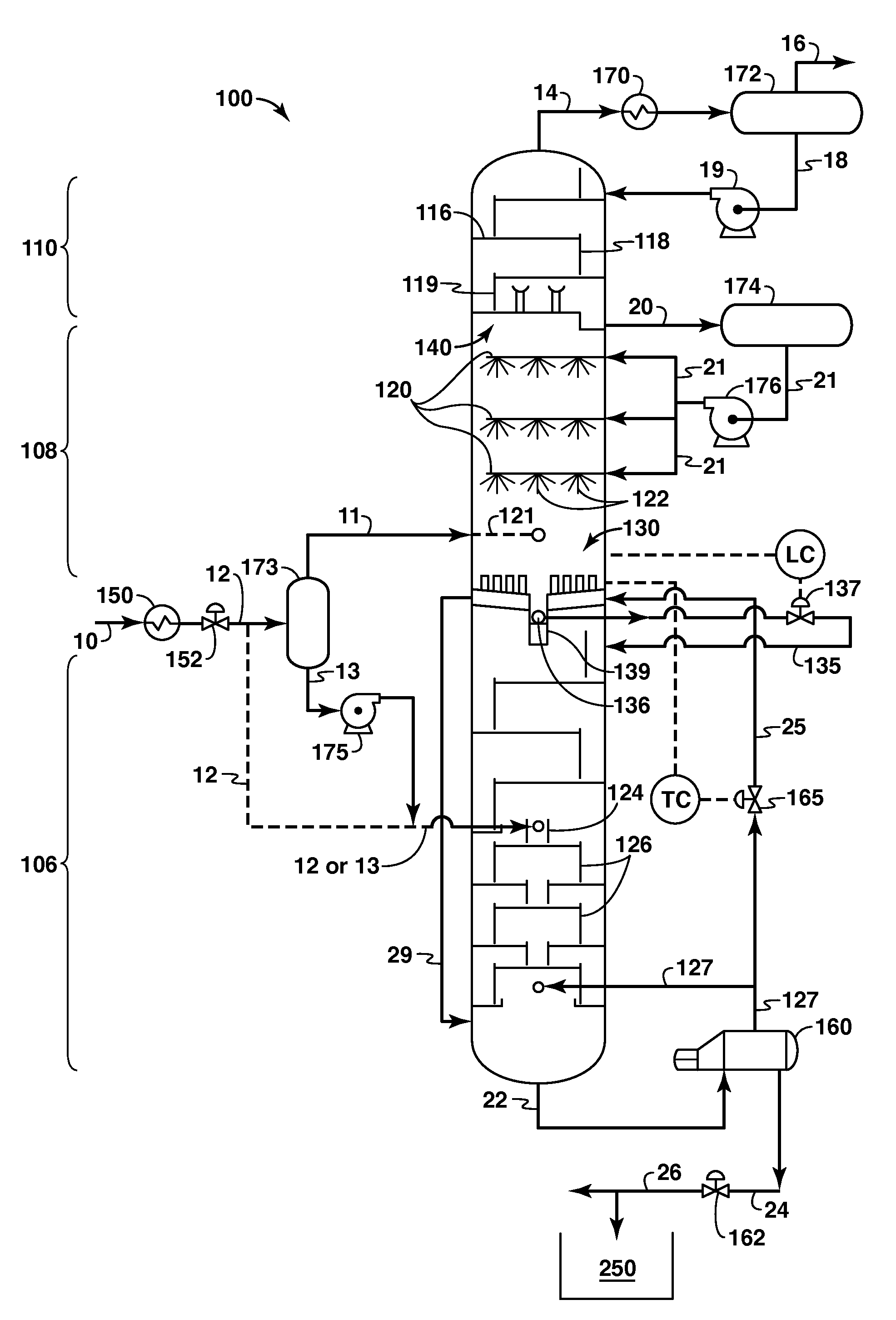
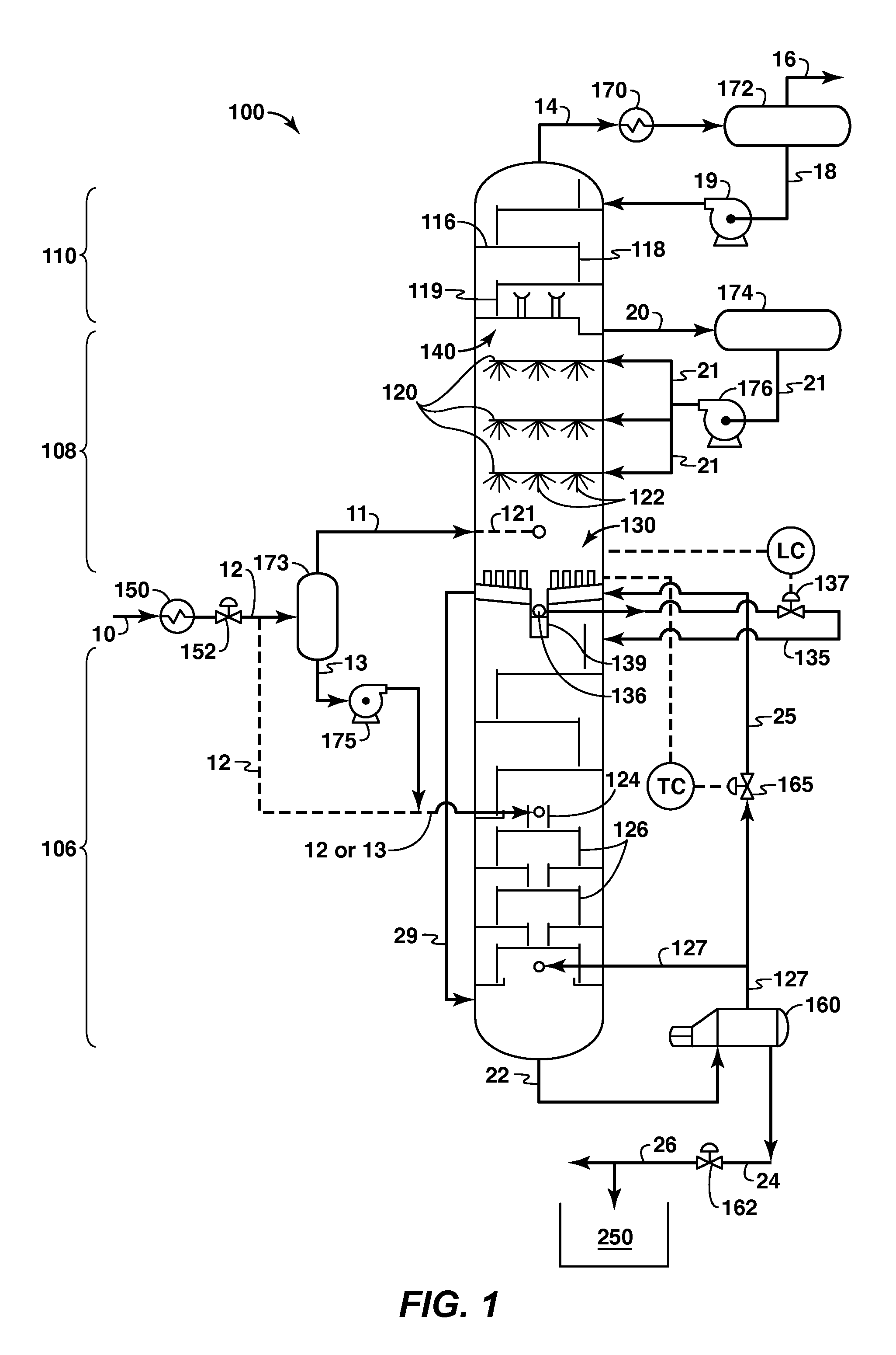
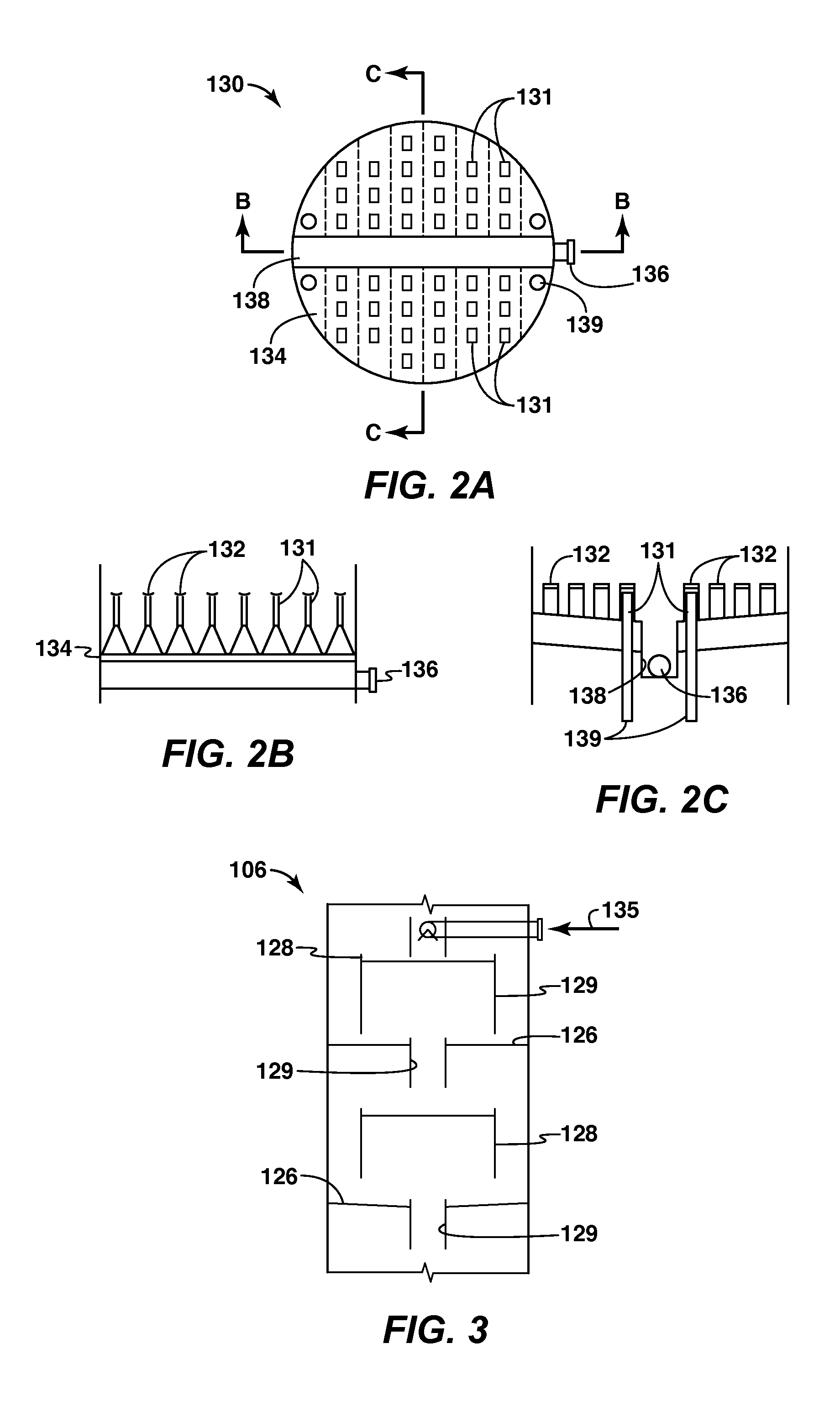
A system for removing acid gases from a sour gas stream is provided. The system includes an acid gas removal system and a heavy hydrocarbon removal system. The acid gas removal system receives the sour gas stream and separates the sour gas stream into an overhead gas stream comprised primarily of methane, and a bottom acid gas stream comprised primarily of acid gases such as carbon dioxide. The heavy hydrocarbon removal system may be placed upstream or downstream of the acid gas removal system or both. The heavy hydrocarbon removal system receives a gas stream and separates the gas stream into a first fluid stream comprising heavy hydrocarbons and a second fluid stream comprising other components. The components of the second fluid stream will depend on the composition of the gas stream. Various types of heavy hydrocarbon removal systems may be utilized.

Description

CROSS REFERENCE[0001]This application claims the benefit of U.S. Provisional Patent Application 61 / 229,994 filed Jul. 30, 2009 entitled CRYOGENIC SYSTEM FOR REMOVING ACID GASES FROM A HYDROCARBON GAS STREAM, WITH REMOVAL OF HEAVY HYDROCARBONS and U.S. Provisional Patent Application 61 / 357,358 filed Jun. 22, 2010 entitled SYSTEMS AND METHODS FOR REMOVING HEAVY HYDROCARBONS AND ACID GASES FROM A HYDROCARBON GAS STREAM. The entirety of both applications are incorporated by reference herein by reference for all purposes.BACKGROUND[0002]This section is intended to introduce various aspects of the art, which may be associated with exemplary embodiments of the present disclosure. This discussion is believed to assist in providing a framework to facilitate a better understanding of particular aspects of the present disclosure. Accordingly, it should be understood that this section should be read in this light, and not necessarily as admissions of prior art.FIELD[0003]The present invention r...

Claims


Application Information

Patent Timeline
IPC IPC(8): F25J3/02B01D53/04B01D50/00B01D53/02
CPCC07C7/005F25J2280/40Y02C10/12C07C7/04F25J2270/60C10L3/104F25J3/0209F25J3/0233F25J3/0238F25J3/0266F25J2200/02F25J2200/74F25J2200/76F25J2205/04F25J2205/40F25J2205/50F25J2205/60F25J2205/64F25J2205/66F25J2205/80F25J2220/66F25J2240/02F25J2240/30F25J2240/40F25J2260/20F25J2270/12C07C9/04F25J2205/10Y02C20/40Y02P20/151
Inventor NORTHROP, PAUL SCOTTKIMBLE, EDWARD L.MART, CHARLES J.SIBAL, PAUL W.KELLEY, BRUCE T.
Owner NORTHROP PAUL SCOTT
Learn More