Positioning catheters using impedance measurement

a technology of impedance measurement and positioning catheter, which is applied in the field of positioning catheters using impedance measurement, can solve the problems of lag period in the method, insufficient accuracy, stepwise increase in impedance, and stress on the patient, so as to reduce the impedance, increase the impedance, and increase the impedance

Inactive Publication Date: 2012-03-29
BIOTRONIK SE & CO KG
View PDF5 Cites 90 Cited by
  • Summary
  • Abstract
  • Description
  • Claims
  • Application Information

AI Technical Summary

Benefits of technology

[0008]The feature of the present invention is to lessen or prevent one or more disadvantages of the prior art. In particular, new ways to position a catheter in a blood vessel shall be provided.
[0018]The two electrodes are disposed on the catheter at a defined distance from each other along the longitudinal axis of the cathether, preferably close to the end of the catheter that is inserted into the blood vessel. The distance between the two electrodes can be selected such that a stent can be installed or crimped between the two electrodes, and / or the catheter has a dilatable region e.g. a deflatable balloon. If the catheter should carry a stent between the two electrodes, the stent can be fastened to the catheter in a manner such that the stent is not connected to any electrode of the catheter in an electrically conductive manner, although the stent itself can be electrically conductive. While the catheter is being advanced in the blood vessel, the stent is preferably in contact with the surrounding blood vessel in a manner such that electrically conductive contact between the stent and the surrounding blood is made possible.
[0019]The catheter can also have more than two electrodes for measuring impedance. If e.g. a plurality of electrodes is used on different lateral surfaces of the catheter, e.g. four electrodes, with two electrodes each on opposite sides of the catheter, it is possible to reduce the influence of an undesired contact with the vessel wall on the impedance signal that is measured.
[0032]The method according to the invention does not require the use of x-rays, thereby ensuring that, overall, the patient is exposed to a lower radiation dose or none at all when a stent is applied. The method according to the invention tracks the advance of the catheter in real time and, overall, does not lengthen the treatment time.
[0033]Given that the method according to the invention makes it possible to locate the optimal position for the application of the stent or the balloon before expansion is performed, the reliability of the vascular expansion and stabilization by stents or balloon catheters is improved overall.
[0034]Since positioning can be performed in an optimal manner, combined with the fact that an incorrect stent length can be detected at an early point in time, the use of a method according to the invention results in improved therapeutic success overall.

Problems solved by technology

The previous imaging methods have a few disadvantages, such as a lag period in the method, insufficient accuracy, additional costs, stressing the patient e.g. via the dosage of radiation, to name a few.
In particular, the entrance of each of the two electrodes into the region of a constriction of the blood vessel independently of each other results in a stepwise increase in impedance, and the exiting of each of the two electrodes out of the region of constriction of the blood vessel results in a stepwise decrease in impedance across the two electrodes.
As a result, the entry and exit of each of the two electrodes into or out of the region of the change in vascular cross section results, in either case, in a ramp-type change in impedance across the two electrodes.
In particular, the entrance of each of the two electrodes into the region of a constriction of the blood vessel can result in a ramp-shaped increase in impedance across the two electrodes, and the emergence of each of the two electrodes from the region of constriction of the blood vessel can result in a ramp-shaped decrease in impedance across the two electrodes.

Method used


Image

  • Positioning catheters using impedance measurement
  • Positioning catheters using impedance measurement
  • Positioning catheters using impedance measurement

Examples


Embodiment Construction

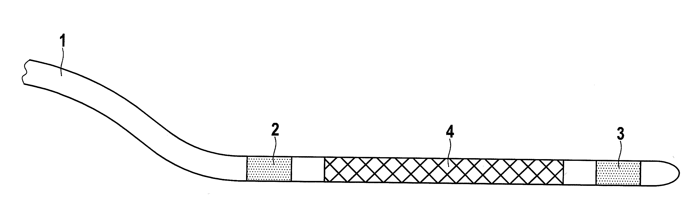
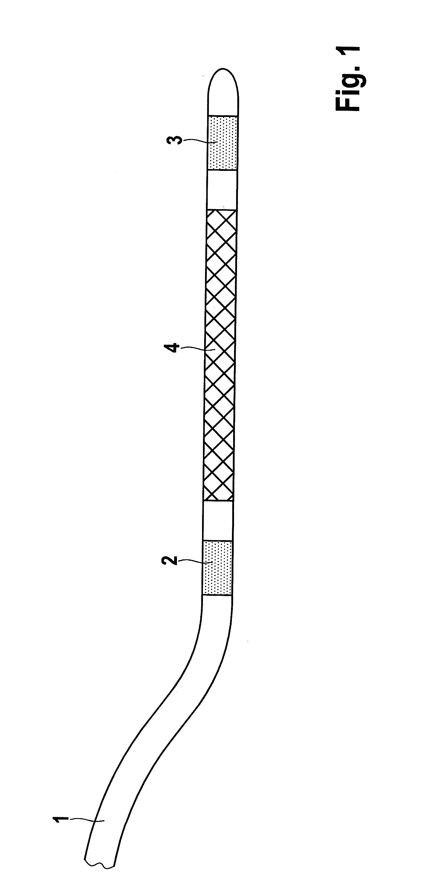
[0041]A catheter that can be used in a method according to the invention is depicted schematically in FIG. 1. The catheter includes a base body 1 and has two electrodes, 2 and 3, close to the end that is introduced into the blood vessel. Electrodes 2 and 3 are disposed on base body 1, separated by a distance in the longitudinal axial direction. A stent 4 is placed between electrodes 2 and 3; once stent 4 has been positioned, it can be applied in the blood vessel via expansion. This stent can be in electrically conductive contact, or not, with the surrounding blood while the catheter is being positioned in the blood vessel.

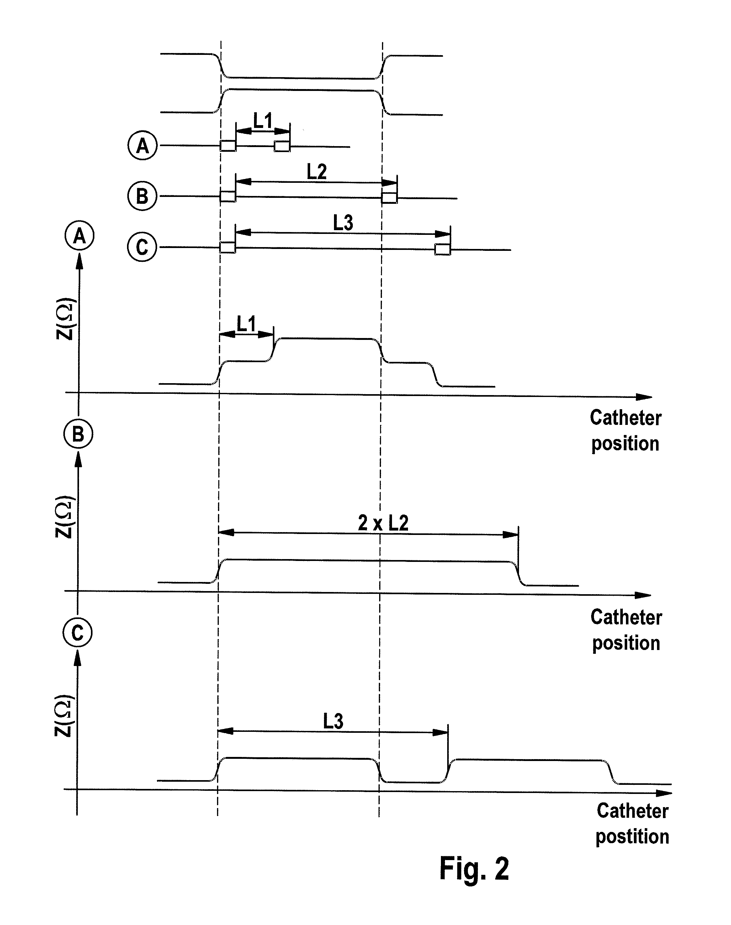
[0042]The catheter shown in FIG. 1 can be positioned using a method according to the invention such that stent 4 is located in an optimal position in the region of a stenosis. For this purpose, the catheter is first introduced into the vascular system, and is then advanced in a suitable manner toward the constriction in the blood vessel to be treated. During the ad...


PUM


Abstract

The invention relates to a method for determining the position of a catheter in a blood vessel relative to a change in the vascular cross section, comprising the steps: providing a catheter that includes at least two electrodes which can be brought into electrically conductive contact with the surrounding blood while the catheter is being positioned in the blood vessel, wherein the two electrodes are installed on the catheter along the longitudinal axis at a defined distance from each other; advancing the catheter in the vessel to be treated, toward the change in the vascular cross section; and measuring the impedance across the two electrodes while the catheter is being advanced; and to a catheter for use in a method of this type.

Description

CROSS REFERENCE TO RELATED APPLICATION[0001]This patent application claims the benefit of U.S. Provisional Patent Application No. 61 / 385,567, filed on Sep. 23, 2010, which is hereby incorporated by reference in its entirety.TECHNICAL FIELD AND BACKGROUND[0002]Angioplasty, or percutaneous transluminal angioplasty (PTA) or percutaneous transluminal coronary angioplasty (PTCA), is a method for expanding or reopening blood vessels that have become constricted or closed (usually arteries, and to a lesser extent veins). Common methods of angioplasty are balloon dilation and the application of stents.[0003]In the fields of interventional radiology, cardiology, and angiology, balloon dilation is understood, within the scope of angioplasty, to mean a method for expanding pathologically constricted blood vessels using a balloon catheter i.e. a vascular catheter with a balloon installed thereon that is expanded slowly under high pressure (6-20 bar) once it has reached the constricted site. The...

Claims


Application Information

Patent Timeline
IPC IPC(8): A61F2/84
CPCA61B5/0538A61B5/1076A61F2250/0096A61F2/958A61F2250/0001A61B5/6852
Inventor VOLLKRON, MICHAELLIPPERT, MICHAEL
Owner BIOTRONIK SE & CO KG
Why Eureka
Try Eureka