Eureka AIR delivers breakthrough ideas for toughest innovation challenges, trusted by R&D personnel around the world.

Dynamic QoS upgrading

Active Publication Date: 2012-03-22
APPLE INC
View PDF10 Cites 21 Cited by
  • Summary
  • Abstract
  • Description
  • Claims
  • Application Information

AI Technical Summary

Benefits of technology

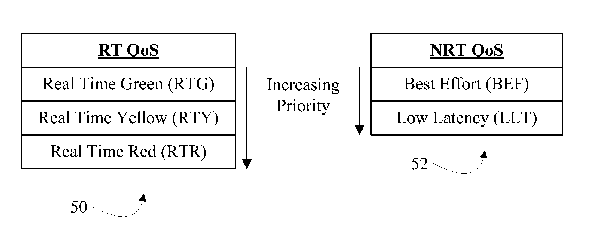
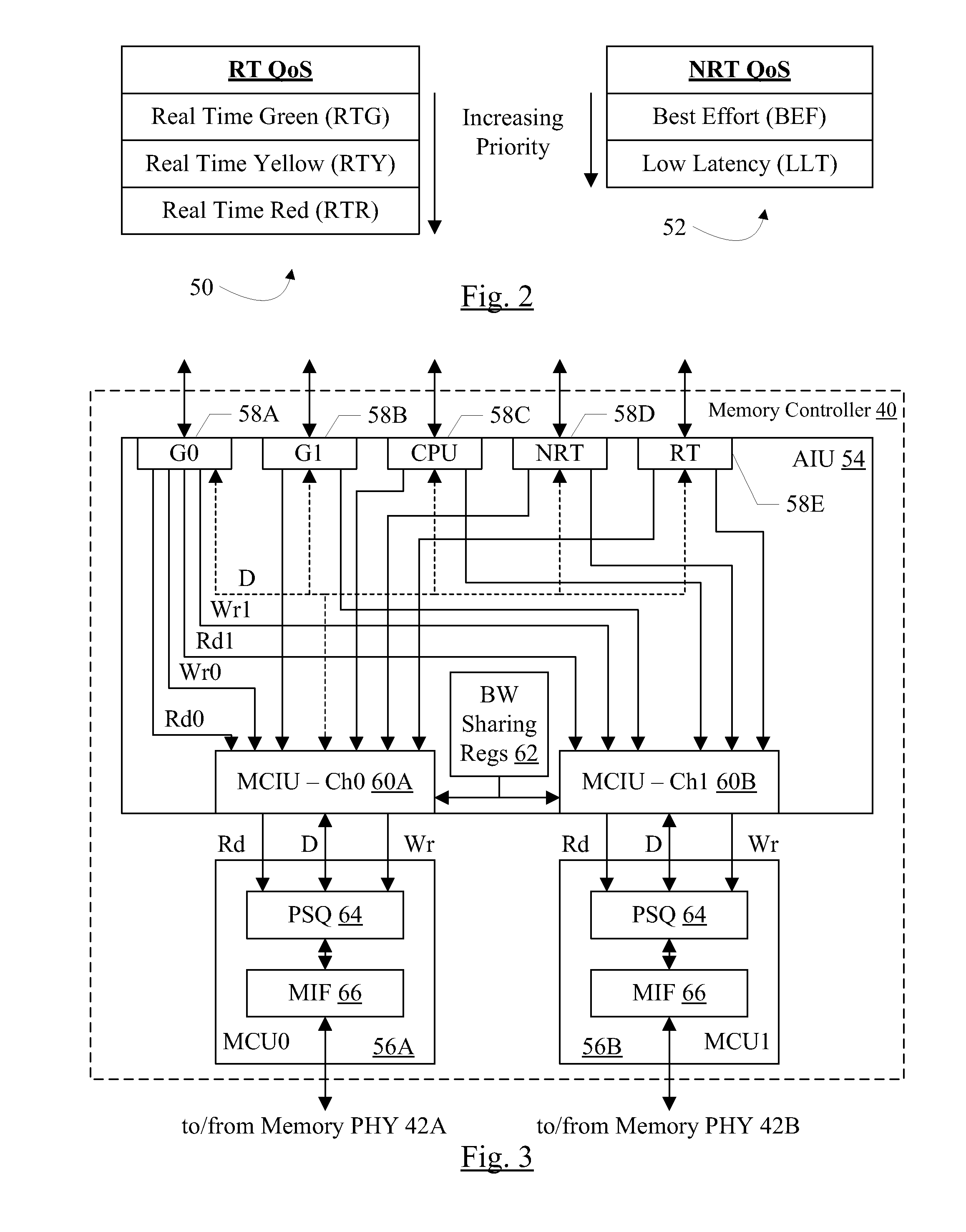
[0008]In one embodiment, a memory controller is coupled to receive memory operations from multiple sources. Each source may assign a quality of service (QoS) parameter to each memory operation transmitted by that source. The memory controller may schedule the memory operations to access memory, and the QoS parameters assigned to the memory operations may be included in the scheduling determination. Additionally, in some embodiments, the memory controller may support upgrade of the QoS parameters of pending memory operations when a subsequent memory operation from the same flow is received with a QoS parameter specifying a higher QoS level than the pending memory operations. The QoS parameters of the pending memory operation may be made equal to the QoS parameter of the newly-received memory operation. In this fashion, the memory controller may more quickly react to the increased needs of the flow. That is, the increase in QoS parameter for the memory operation may indicate that the flow is not receiving data quickly, and thus increasing the QoS of the pending memory operations to the QoS of the newly-received operation may increase the rate at which the pending operations are serviced.

Problems solved by technology

The memory system is volatile, retaining data when powered on but not when powered off, but also provides low latency access as compared to nonvolatile memories such as Flash memory, magnetic storage devices such as disk drives, or optical storage devices such a compact disk (CD), digital video disk (DVD), and BluRay drives.
Memory controllers have limited visibility to the different types of traffic that can be issued by the sources.
Accordingly, memory controllers have not been able to segregate traffic at finer levels of granularity.
Thus, performance improvements in memory controllers have been limited to the coarser mechanisms such as scheduling read operations prior to write operations.

Method used


Image

  • Dynamic QoS upgrading
  • Dynamic QoS upgrading
  • Dynamic QoS upgrading

Examples


Embodiment Construction

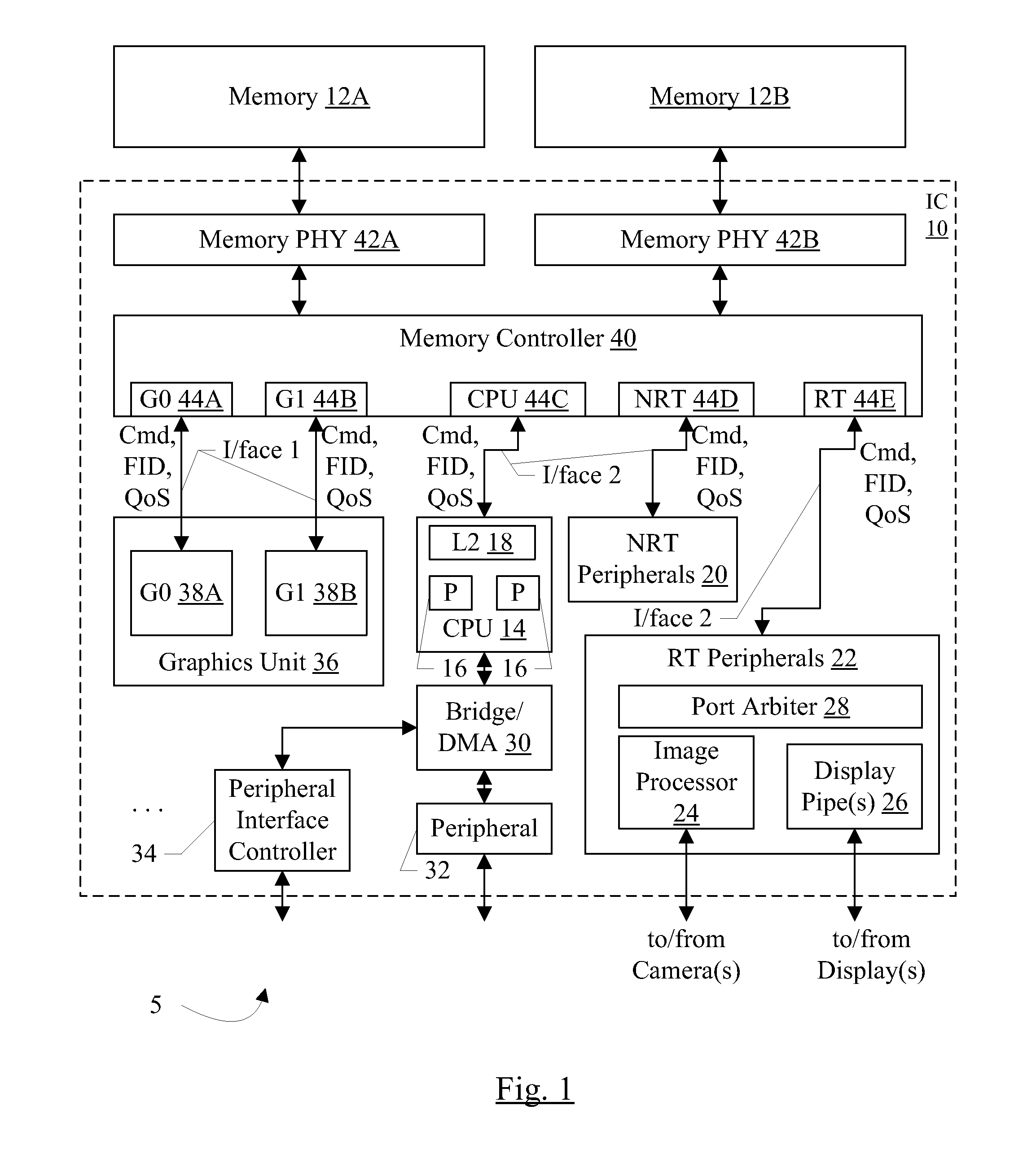
[0035]Turning now to FIG. 1, a block diagram of one embodiment of a system 5 is shown. In the embodiment of FIG. 1, the system 5 includes an integrated circuit (IC) 10 coupled to external memories 12A-12B. In the illustrated embodiment, the integrated circuit 10 includes a central processor unit (CPU) block 14 which includes one or more processors 16 and a level 2 (L2) cache 18. Other embodiments may not include L2 cache 18 and / or may include additional levels of cache. Additionally, embodiments that include more than two processors 16 and that include only one processor 16 are contemplated. The integrated circuit 10 further includes a set of one or more non-real time (NRT) peripherals 20 and a set of one or more real time (RT) peripherals 22. In the illustrated embodiment, the RT peripherals include an image processor 24, one or more display pipes 26, and a port arbiter 28. Other embodiments may include more or fewer image processors 24, more or fewer display pipes 26, and / or any a...


PUM


Abstract

In an embodiment, a memory controller includes multiple ports. Each port may be dedicated to a different type of traffic. In an embodiment, quality of service (QoS) parameters may be defined for the traffic types, and different traffic types may have different QoS parameter definitions. The memory controller may be configured to scheduled operations received on the different ports based on the QoS parameters. In an embodiment, the memory controller may support upgrade of the QoS parameters when subsequent operations are received that have higher QoS parameters, via sideband request, and / or via aging of operations. In an embodiment, the memory controller is configured to reduce emphasis on QoS parameters and increase emphasis on memory bandwidth optimization as operations flow through the memory controller pipeline.

Description

BACKGROUND[0001]1. Field of the Invention[0002]This invention is related to the field of memory controllers.[0003]2. Description of the Related Art[0004]Digital systems generally include a memory system formed from semiconductor memory devices such as static random access memory (SRAM), dynamic random access memory (DRAM), synchronous DRAM (SDRAM), double data rate (DDR, DDR2, DDR3, etc.) SDRAM including low power versions (LPDDR, LPDDR2, etc.) SDRAM, etc. The memory system is volatile, retaining data when powered on but not when powered off, but also provides low latency access as compared to nonvolatile memories such as Flash memory, magnetic storage devices such as disk drives, or optical storage devices such a compact disk (CD), digital video disk (DVD), and BluRay drives.[0005]The memory devices forming the memory system have a low level interface to read and write the memory according to memory device-specific protocols. The sources that generate memory operations typically co...

Claims


Application Information

Patent Timeline
IPC IPC(8): G06F12/00
CPCG06F13/1694G06F13/1684
Inventor BISWAS, SUKALPACHEN, HAOWADHAWAN, RUCHI
Owner APPLE INC
Why Eureka
Eureka Blog
Learn More