Eureka AIR delivers breakthrough ideas for toughest innovation challenges, trusted by R&D personnel around the world.

Method and Apparatus for Fast Fault Detection

Active Publication Date: 2010-02-04
NORTHROP GRUMMAN SYST CORP
View PDF23 Cites 16 Cited by
  • Summary
  • Abstract
  • Description
  • Claims
  • Application Information

AI Technical Summary

Benefits of technology

[0015]A method and apparatus are therefore provided to detect, in some embodiments, high-impedance faults on poly-phase power systems both accurately and quickly including, for example, when the fault is an arc fault, or other high-impedance fault, that is dissipating a fraction of normal full load power. In one embodiment, a method and apparatus are provided that utilize phase voltages and an imbalance reference value as inputs to a rectifier and a synchronous band pass filter with a finite gain to detect a fault. By detecting a fault in this manner, erroneous tripping can be avoided and a fault can be detected and reacted to quickly.

Problems solved by technology

The results of faults can include fires, smoke, and melted or vaporized power system components.
Further, due to the prospects of, for example, aging wiring in civilian and military aircraft, and the reduced thickness of insulation of modern wires, the likelihood of faults on power systems is increasing.
Often high-impedance faults can generate current levels similar to or less than normal load current.
Accordingly, catastrophic damage to system components can result because the fault remains on the system for a substantial duration.
Many issues challenge the performance of any fault detection scheme.
Conventional protection devices, such as fuses, breakers, and the like, cannot meet this requirement because these devices only protect against currents exceeding full load.
Conventional time-over-current devices may take from seconds to minutes to operate, which can be too long to effectively protect system components.
Although this scheme is simple and effective for both AC and DC circuits, splitting each load wire in two is not always practical.
This system is also effective for any type of AC or DC power system, but it introduces considerable complexity to a power system protection scheme.
As a result, this scheme is unlikely to find use in, for example, an airborne application.
This scheme, however, requires at least two relays and current sensors, which are not always available and require regular maintenance to ensure accurate operation.
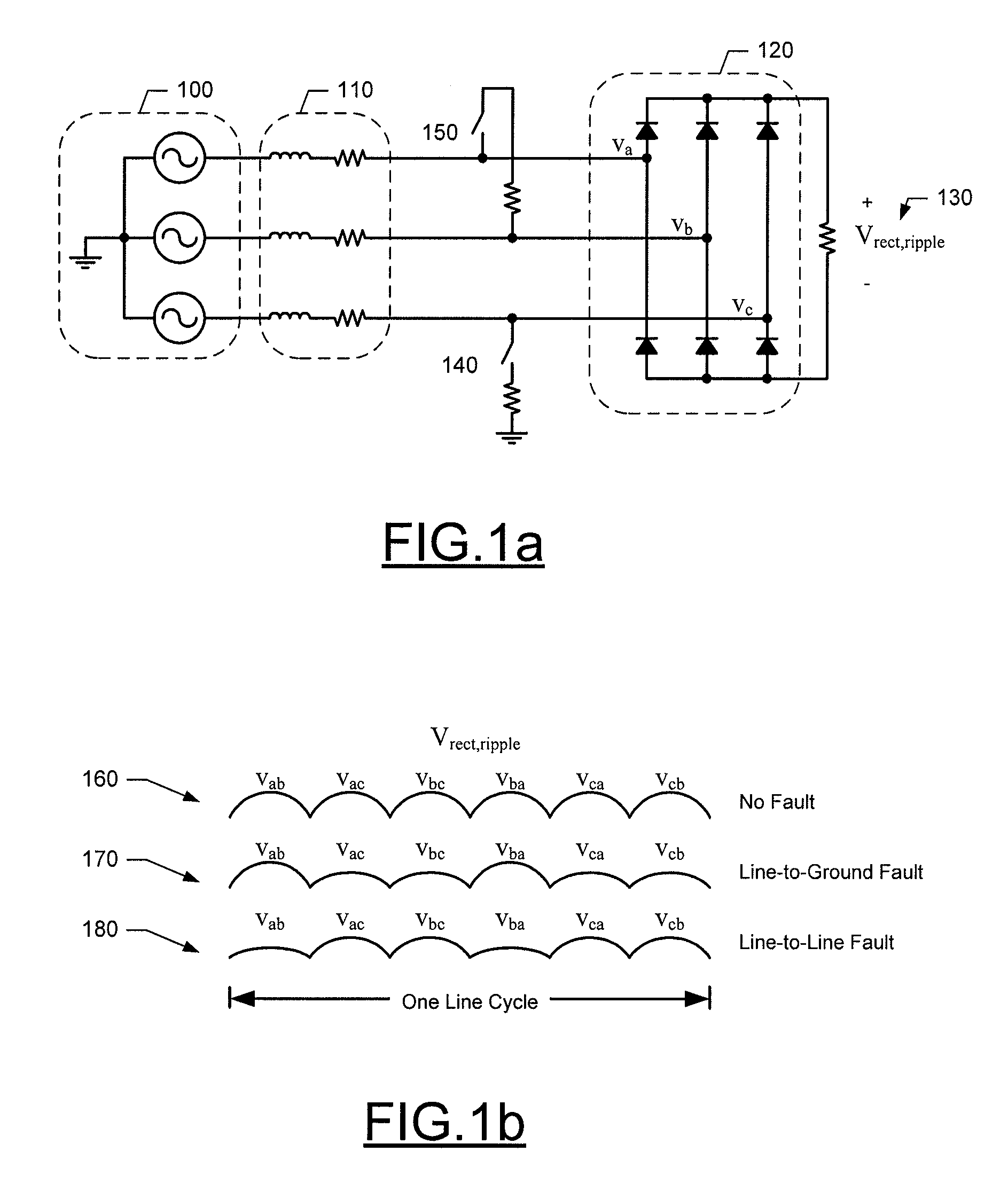
As such, when a high-impedance fault is present, conventional current sensing devices may not detect a change, but devices that are attentive to the harmonics on the power system can detect the presence of a high-impedance fault.
In imbalanced power systems first and second harmonics can arise as a result of the imbalanced load.
However, when fault conditions occur on an imbalanced power system, the first and second harmonic component of the waveform at the rectifier output will still increase.
Further, the source impedance of an AC power system can affect the harmonic content of a system waveform under fault conditions.
Thus, in applications where alteration of the power system waveform is undesirable, the Humbucker solution is inapplicable.

Method used


Image

  • Method and Apparatus for Fast Fault Detection
  • Method and Apparatus for Fast Fault Detection
  • Method and Apparatus for Fast Fault Detection

Examples


Embodiment Construction

[0025]Embodiments of the present invention will now be described more fully hereinafter with reference to the accompanying drawings, in which some, but not all embodiments of the invention are shown. Indeed, the invention may be embodied in many different forms and should not be construed as limited to the embodiments set forth herein; rather, these embodiments are provided so that this disclosure will satisfy applicable legal requirements. Like reference numerals refer to like elements throughout. Moreover, the term “exemplary,” as used herein, is not provided to convey any qualitative assessment, but instead to merely convey an illustration of an example.

[0026]FIG. 3. illustrates a block diagram of a power system 300 that provides for fault detection in accordance with embodiments of the present invention. The power system includes a power source 310, interrupting device 320, a load element 330, a tap point 340, and a fault detector 350 according to an embodiment of the invention....


PUM


Abstract

A method and apparatus are provided for detecting a fault condition on a power system. By rectifying power system phase voltages to produce a rectified waveform, and filtering the rectified waveform or a representation of the rectified waveform through a finite gain synchronous band pass filter to generate a synchronous band pass filter output waveform that indicates the magnitude of a predefined harmonic frequency component, a fault condition on a power system can be identified.

Description

TECHNOLOGICAL FIELD[0001]Embodiments of the present invention relate generally to electrical system protection and, more particularly, relate to a method and apparatus for detecting fault conditions on electrical systems.BACKGROUND[0002]Many conventional poly-phase power systems utilize some means to protect the system against faults. Faults, such as line-to-line and line-to-ground faults, can cause considerable damage to power system equipment, and as such, protection against faults is desirable. The results of faults can include fires, smoke, and melted or vaporized power system components. Further, due to the prospects of, for example, aging wiring in civilian and military aircraft, and the reduced thickness of insulation of modern wires, the likelihood of faults on power systems is increasing.[0003]Faults can be low-impedance or high-impedance. In the presence of low-impedance faults, current flow on a system can increase substantially, far exceeding the normal load current on t...

Claims


Application Information

Patent Timeline
IPC IPC(8): G01R23/00
CPCG01R31/025H02H3/52H02H1/0015G01R31/088G01R31/52
Inventor WUNDERLICH, SCOTTGARLAND, GERALD ANDREW
Owner NORTHROP GRUMMAN SYST CORP
Why Eureka
Eureka Blog
Learn More