Eureka AIR delivers breakthrough ideas for toughest innovation challenges, trusted by R&D personnel around the world.

Actuating device for a safety means

Inactive Publication Date: 2005-03-17
TRW OCCUPANY RESTRAINT SYST
View PDF32 Cites 10 Cited by
  • Summary
  • Abstract
  • Description
  • Claims
  • Application Information

AI Technical Summary

Benefits of technology

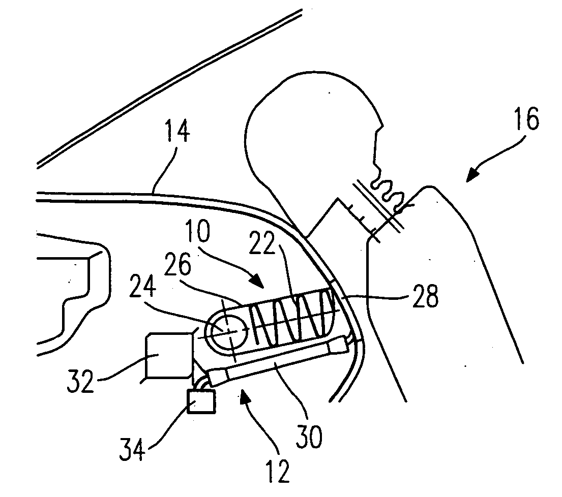
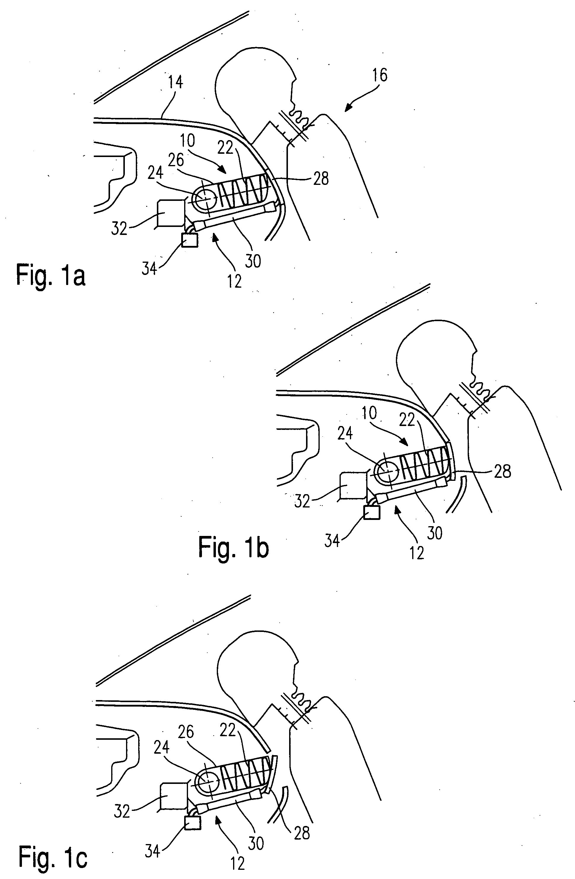
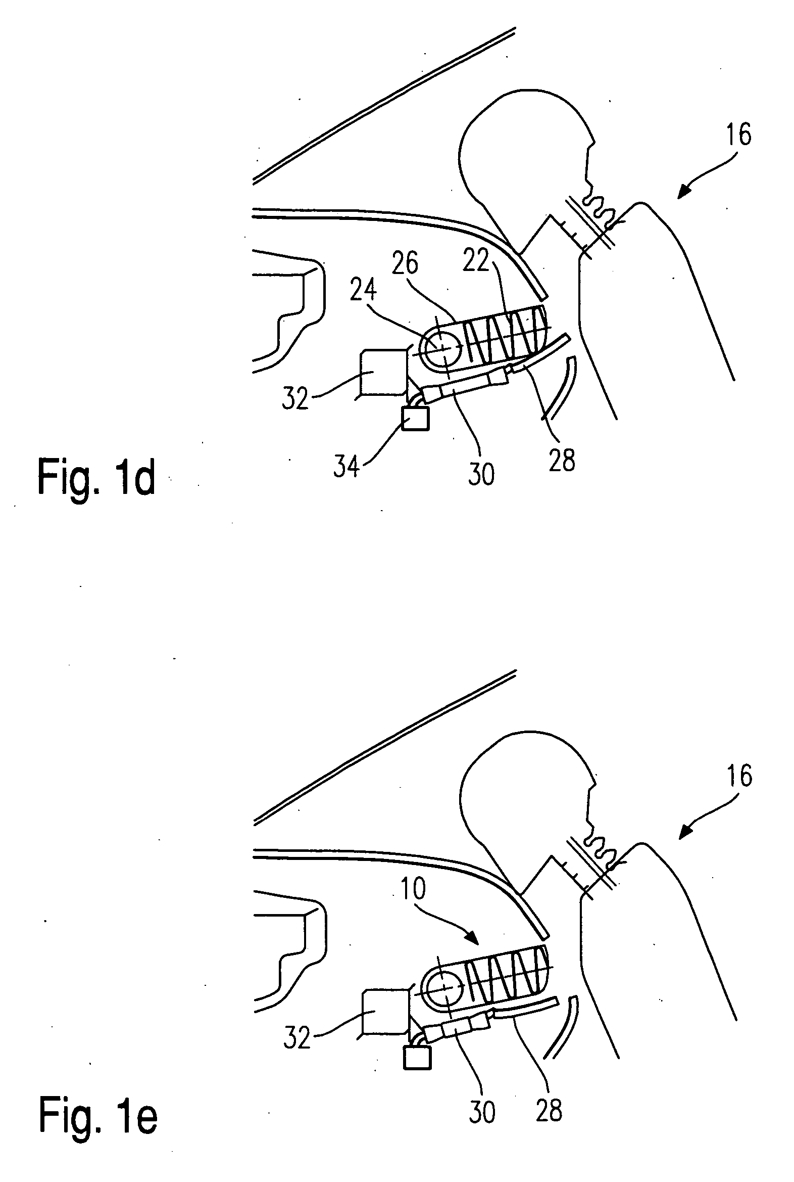
[0004] According to the invention, an actuating device is provided which has a pneumatic muscle as drive and a pyrotechnical gas generator for feeding the pneumatic muscle. Pneumatic muscle is understood here to be a fluid-operated actuating device, as it is described for instance in DE 195 31 097 A1. The pneumatic muscle consists of a tubular body, which is surrounded by a sleeve with a net-like structure. When the tubular body is pressurized, this leads to a radial expansion, which due to the net structure of the sleeve results in a longitudinal contraction of the muscle. In the case of activation, an actuating device with such pneumatic muscle can react very quickly, because in contrast to a piston-cylinder drive no piston mass has to be accelerated. Since the pyrotechnical gas generator can produce a sufficient amount of gas with the required pressure within fractions of a second, the safety means can be activated very quickly by the actuating device, so that in the case of an accident the protective effect can be produced in good time and effectively. In addition, the pneumatic muscle is flexible, so that the actuating device in the vehicle can be bent during installation and thus be mounted even at hardly accessible points and can also be laid in curved fashion.

Problems solved by technology

Piston-cylinder drives are inflexible and mostly bulky, as they must have a linear travel path for the piston.
This is impeded by the mass inertia of moving parts.

Method used


Image

  • Actuating device for a safety means
  • Actuating device for a safety means
  • Actuating device for a safety means

Examples


second embodiment

[0033] the assembly according to the invention can be seen in FIGS. 2 and 3. On a schematically represented truck 110 with a loading area 112 a cargo 114 is disposed, which is secured with a tensioning belt 116. The two ends of the tensioning belt 116 are attached to the loading area 112 on the lower side thereof and are each passed through one of two eyes 118 of a tensioning device. For tensioning the tensioning belt 116, the two eyes 118 are movable parallel to the plane of the loading area 112. The tensioning device can be actuated by an actuating device 122 comprised of a pneumatic muscle 130 and a pyrotechnical gas generator 132. For this purpose, the ends of the pneumatic muscle 130 are each connected with one of the eyes 118. For activating the tensioning device, the pneumatic muscle 130 is pressurized so that it contracts in the known manner, thereby moving the eyes 118 towards each other such that the tensioning belt 116 is tensioned.

[0034] An additional mechanical lock can...

eighth embodiment

[0052] In FIGS. 19 and 20 there is shown an This embodiment concerns a bumper 600 which can be transferred by means of an actuation device from the neutral position shown in FIG. 19 into the activated position shown in FIG. 20 in which it is extended with respect to the neutral position by a distance A. For displacing the bumper 600 there is used an actuating device 622 which employs a pneumatic muscle 630 as well as two knee links 636 as they are known from FIG. 15. Each knee link is connected on one end fixedly with the vehicle and on the other end with the bumper 600, a tie member 634 engaging at the center and being connected with the pneumatic muscle 630.

[0053] By activating the pneumatic muscle 630, the distance between the two knee links 636 lying opposite each other is shortened such that the bumper is transferred into the position shown in FIG. 20. This allows an early contact with the other party involved in the accident. The actuation device may be constructed here in su...

ninth embodiment

[0055] In the ninth embodiment, too, the pneumatic muscle 330 is used both for tensioning the end fitting 316 and the belt buckle 320. Provided for activation is a gas generator 359 which in case of need is activated by a trigger circuit (not shown).


PUM


Abstract

An actuating device for a safety arrangement in a vehicle has a pneumatic muscle as drive and a pyrotechnical gas generator for feeding the pneumatic muscle.

Description

TECHNICAL FIELD [0001] This invention relates to an actuating device for a safety means in a vehicle, and an assembly consisting of a safety means and such actuating device. BACKGROUND OF THE INVENTION [0002] Such actuating devices have so far been designed as compressed-gas-operated piston-cylinder units or electric drives. Piston-cylinder drives are inflexible and mostly bulky, as they must have a linear travel path for the piston. An important prerequisite for the use for a safety means is the reaction time, i.e. how fast can the actuating device activate the protection means to such an extent that the protective effect is obtained. This is impeded by the mass inertia of moving parts. It is often attempted to compensate this obstacle by over dimensioning the drive, whereby space requirement and weight of the actuating device are increased. [0003] The invention provides an actuating device requiring little space, which can flexibly be accommodated in the vehicle and has a very sho...

Claims


Application Information

Patent Timeline
IPC IPC(8): B60N2/42B62D25/10B60N2/427B60P7/08B60P7/15B60R19/20B60R19/40B60R21/00B60R21/02B60R21/08B60R21/215B60R21/2155B60R21/34B60R21/38B60R22/195B60R22/26B60R22/46F15B15/10
CPCB60N2/4221B60R2022/4614B60N2/42727B60N2/4279B60P7/0838B60R19/40B60R21/02B60R21/08B60R21/215B60R21/2155B60R21/38B60R22/1952B60R22/1954B60R22/1955B60R22/26B60R2021/0046B60R2021/0213B60N2/42718
Inventor BIRK, KARLCLASS, UWEDANNENHAUER, REINERLUDERS, MICHAELMIODEK, THOMASHASBACH, THOMAS
Owner TRW OCCUPANY RESTRAINT SYST
Why Eureka
Eureka Blog
Learn More