
Mixing and dispensing apparatus for bone void filler

a technology of mixing apparatus and filler, which is applied in the direction of cement mixing apparatus, mixers, containers, etc., can solve the problems of unsuitable hydraulic setting applications for cementitious pmma materials, the known evacuation system for de-airing cementitious pmma materials is typically unsuitable for hydraulic setting applications, and the expansion of air bubbles in the cohesive paste may remain trapped, etc., to improve x-ray visibility, improve mechanical strength, and increase density

Inactive Publication Date: 2012-03-22
BIOCOMPOSITES
View PDF0 Cites 37 Cited by
  • Summary
  • Abstract
  • Description
  • Claims
  • Application Information

AI Technical Summary

Benefits of technology

The present invention provides a method for preparing a de-aired hydraulic setting bone cement by combining a powder bone substitute material and an aqueous liquid component. By removing air from the powder material and mixing it with the liquid component, the resulting bone cement has improved mechanical strength, increased density, and fatigue resistance. The method also allows for improved X-ray visibility and reduced embolism risk. The de-aired bone cement can be easily injected into bone voids under pressure and is suitable for use in vertebroplasty and kyphoplasty procedures. The method involves evacuating the first container in which the powder material is stored and mixing the evacuated material with the liquid component in a separate container. The mixing can be performed under "no touch" conditions to maintain sterility. The use of a multi-port connector allows for easy removal of the vacuum source and facilitates the transfer of the liquid component from one container to another. Overall, the invention provides a more efficient and effective method for preparing a de-aired hydraulic setting bone cement.

Problems solved by technology

It has been found that known evacuation systems for de-airing cementitious PMMA materials are typically unsuitable for applications involving hydraulic setting bone cements as the cements are formed from an aqueous cohesive paste comprising a highly filled suspension of particulate components in an aqueous medium.
Consequently, it has been found that the expanded air bubbles formed in the cohesive paste by application of a vacuum may remain trapped within the paste rather than rise freely to the surface.
Although it may be possible to dislodge some of the larger air bubbles by shaking or mixing the mixture; removal of the smaller air bubbles is more problematic.
Moreover, mixing the mixture may also cause the entrapped air bubbles to be broken-up into smaller bubbles.
Furthermore, as the cohesive paste progressively sets during the procedure, the viscosity of the paste continuously increases thereby making removal of the entrapped air bubbles even more problematic with the passage of time.

Method used


Image

  • Mixing and dispensing apparatus for bone void filler
  • Mixing and dispensing apparatus for bone void filler
  • Mixing and dispensing apparatus for bone void filler

Examples


example 1

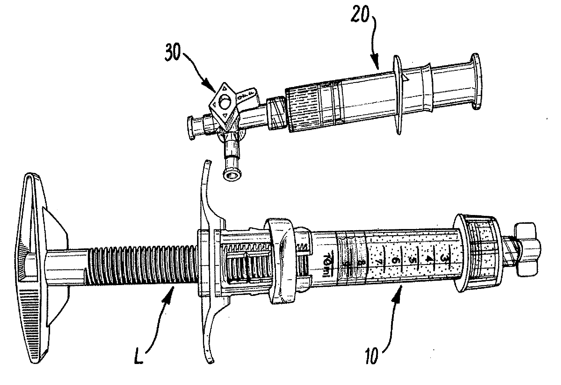
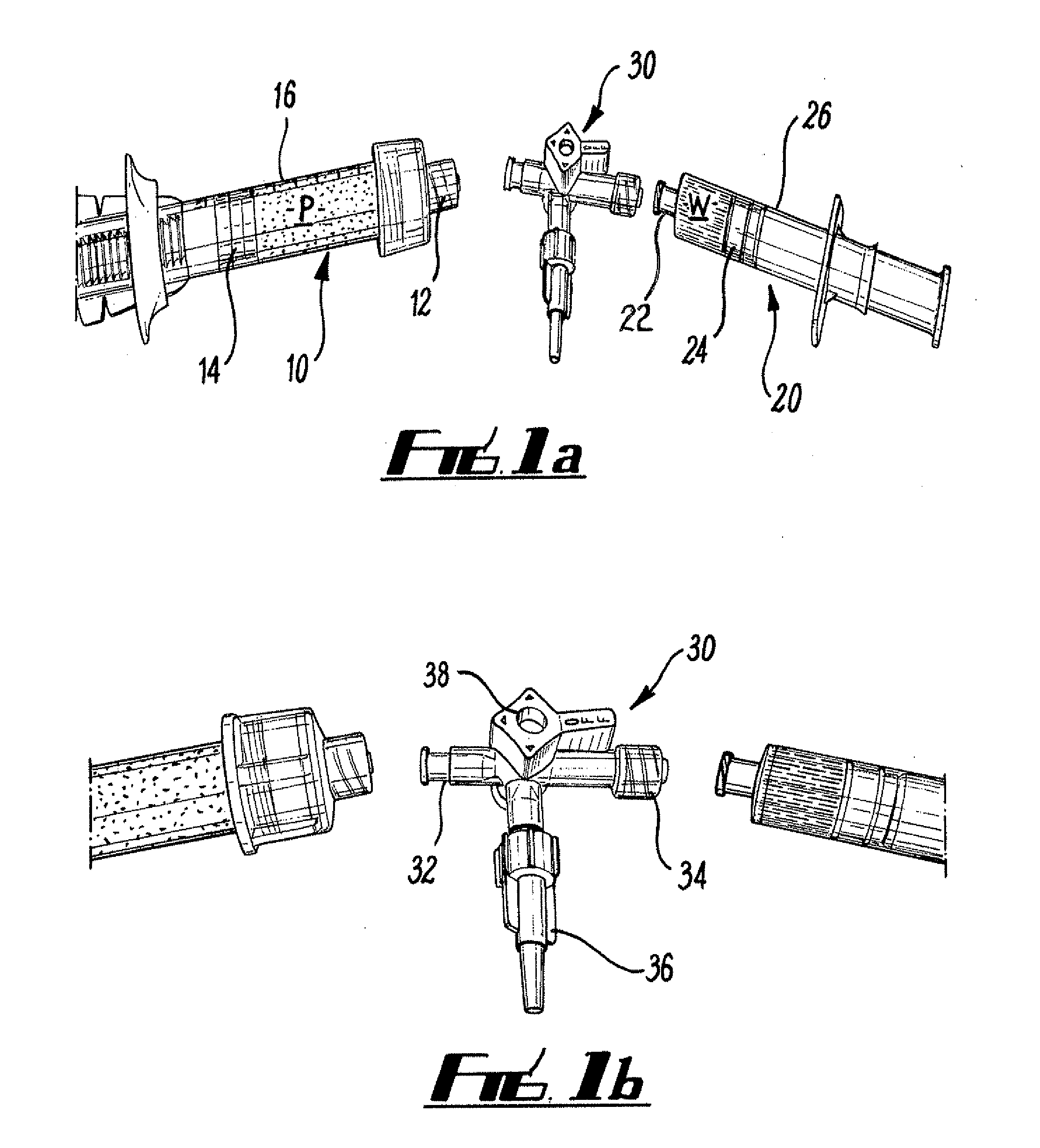
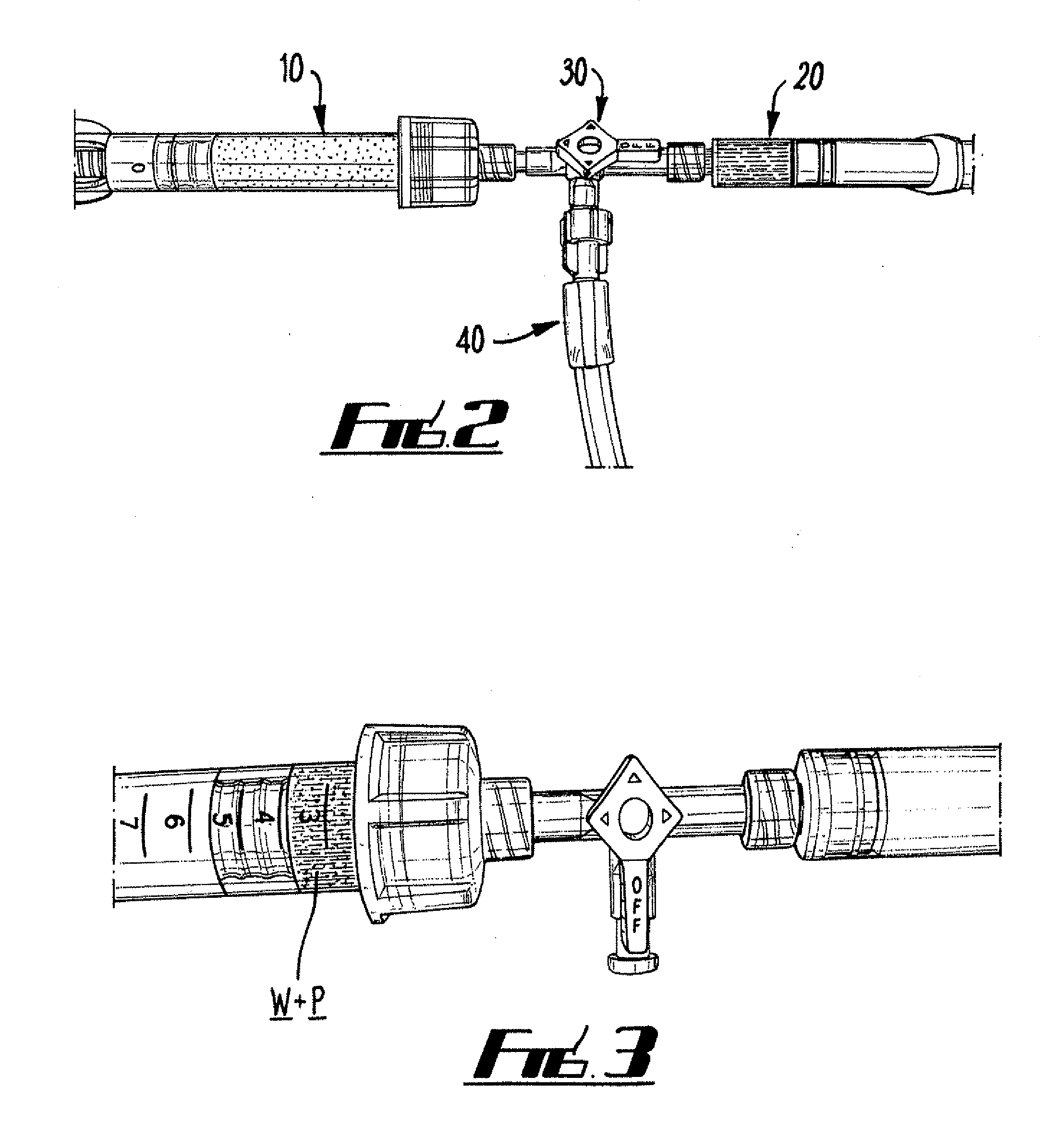
[0051]Referring to FIGS. 1a and 1b there is shown apparatus for preparing a de-aired hydraulic setting hardenable bone cement (i.e. bone void filler). The apparatus comprises a first and second container and a multi-port connector.

[0052]In this example, five grams of calcium sulphate alpha hemi-hydrate powder, P, having a particle size of substantially less than 150 microns is contained in the first container, which comprises a first piston syringe 10. The first piston syringe 10 has a 10 ml capacity and features a male luer-lock connector 12 and a lockable piston 14 within syringe barrel 16. The first syringe is typically supplied to an end user with an end cap in place over the luer-lock to maintain the contents of the syringe to be free of contamination.

[0053]The second container comprises a second piston syringe 20 and this has a female luer-lock connector 22 and a piston 24 moveable within syringe barrel 26. The syringe 20 has a 5 ml capacity and contains 1.7 ml of water, W.

[00...

example 2

[0063]In a second embodiment of the apparatus and method of the invention, which will now be described in relation to FIG. 4, a variation to the method and apparatus described in the first example is made by pre-combining the second syringe 20 and the three-way connector 30.

[0064]The powder component is supplied in a first syringe 10 in the same way as in the first embodiment. However, by supplying the second syringe 20 pre-connected to the three-way connector 30 with the water component contained both within the syringe 20 and the limb of the three-way connector 30 up-to the three-way valve the quantity of air trapped within the system can be minimised before de-airing.

[0065]In use, the end cap is first removed from the luer-lock end 12 of the powder containing syringe 10 which is then screwed onto the corresponding end of the three way tap in an air-tight manner. The evacuation and mixing procedures are then performed as described in Example 1 with the advantage that there is less...

example 3

[0066]A calcium phosphate powder mixture consisting of equimolar amounts of ground Ca4(PO4)2O (tetracalcium phosphate, TTCP) and CaHPO4 (dicalcium phosphate anhydrous, DCPA) was contained within a lockable piston syringe. The corresponding water component was contained within a simple piston syringe. The powder syringe was initially in the locked position. In use, the two syringes were connected together through a ‘T-piece’ connector and evacuation and mixing of the cement components was undertaken as previously described in Example 1.


PUM

PropertyMeasurementUnit
vacuumaaaaaaaaaa
pressureaaaaaaaaaa
relative pressureaaaaaaaaaa

Abstract

A method for preparing a de-aired hydraulic setting hardenable bone cement for filling a boney void or cavity by combining a powder bone substitute material and a aqueous liquid component, the method comprising the steps of: (a) supplying said powder bone substitute material in a first evacuable container; (b) withdrawing air from the first container to form a de-aired powder bone substitute material; and, then (c) mixing the de-aired powder bone substitute material and the aqueous liquid component together.

Description

BACKGROUND OF THE INVENTION[0001]The present invention provides an apparatus and method for producing a de-aired hydraulic setting hardenable bone cement (i.e. a de-aired mixture comprising a bone substitute material and an aqueous liquid component which hardens / fully sets to form a bone cement due to the chemical reaction of the bone substitute material with the aqueous liquid component) suitable for the treatment of bone disorders and filling of boney voids or defects of the skeletal system of the human or animal body. In particular, although not exclusively, the present invention provides a simple means to produce a de-aired hydraulic setting hardenable bone cement in a sterile manner which may be dispensed directly to the surgical site in a convenient and minimally invasive manner, whereby it hardens in-situ to form a de-aired bone cement having desirable mechanical strength and fatigue resistance.[0002]Bone cements in the form of grafts and bone void fillers are used in orthopa...

Claims


Application Information

Patent Timeline
Patent Type & Authority Applications(United States)
IPC IPC(8): A61B17/58B65D83/00B28C7/14C04B28/14C04B12/02
CPCA61B17/8827B01F13/0023B01F11/0071B01F5/0685B01F25/4512B01F31/65B01F33/50112
Inventor COOPER, JOHN JOSEPHBRAYFORD, MICHAEL JAMESWATERS, DAVID RUSSELL
Owner BIOCOMPOSITES
Learn More