
Exhaust gas-purifying catalyst

Active Publication Date: 2012-03-15
CATALER CORP
View PDF15 Cites 21 Cited by
  • Summary
  • Abstract
  • Description
  • Claims
  • Application Information

AI Technical Summary

Benefits of technology

[0010]An object of the present invention is to provide a technique by which excellent exhaust gas purification performances can be achieved.

Problems solved by technology

However, the precious metal has a problem that they are susceptible to poisoning by HC in the exhaust gas.
When the precious metal is poisoned by HC, NOX reduction reaction on the precious metal becomes difficult to occur.
Therefore, a catalyst comprising the precious metal sometimes shows an insufficient NOX purification efficiency specifically under a rich atmosphere in which an HC concentration in the exhaust gas is high.

Method used


Image

  • Exhaust gas-purifying catalyst
  • Exhaust gas-purifying catalyst
  • Exhaust gas-purifying catalyst

Examples


example 1

Preparation of Catalyst C1

[0067]Alumina doped with 10% by mass of barium was prepared. Hereinafter, this is referred to as “Ba alumina BA1”.

[0068]A composite oxide of cerium oxide and zirconium oxide was prepared. In the composite oxide, the molar ratio of the cerium element to zirconium element was 7:3. Hereinafter, this composite oxide is referred to as “CZ oxide”.

[0069]A monolith honeycomb substrate made of cordierite having a entire length of 100 mm, a volume of 1.0 L, and a cell number of 900 per square inch was prepared (1 inch=2.54 cm).

[0070]50 g of Ba alumina BA1, 50 g of CZ oxide, an aqueous solution of palladium nitrate containing 0.5 g of palladium, and 2 g of citric acid were mixed to prepare a slurry. Hereinafter, the slurry is referred to as “slurry S1”.

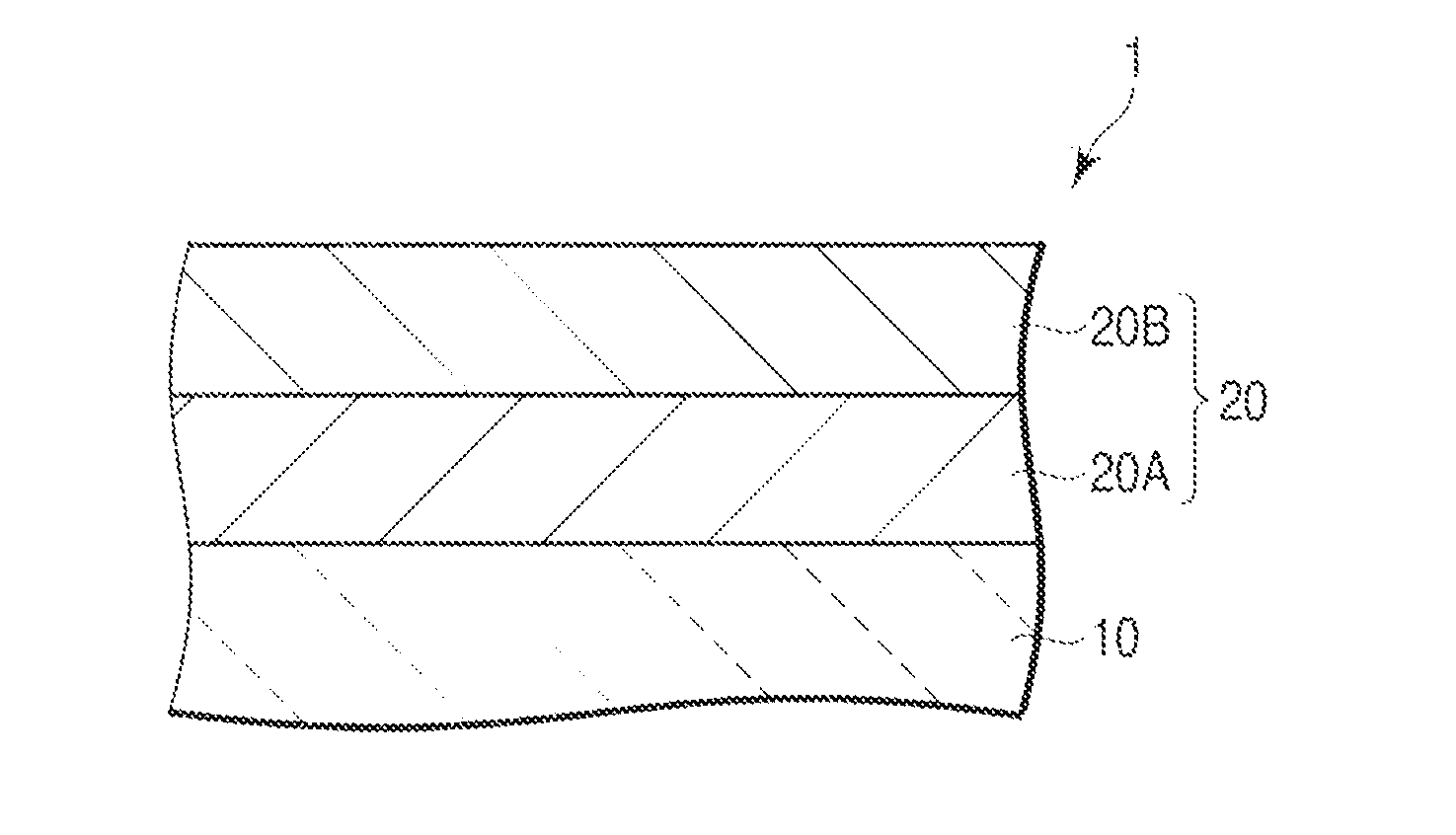
[0071]The slurry S1 was then applied to the above-mentioned substrate. This was then dried at 250° C. for 1 hour, followed by firing at 500° C. for 1 hour. Thus, the first catalytic layer 20A of which the raw material w...

example 2

Production of Catalyst C2

Comparative Example

[0077]45 g of alumina, 50 g of CZ oxide, 8.5 g of barium sulfate, an aqueous solution of palladium nitrate containing 0.5 g of palladium, and 2 g of citric acid were mixed to prepare a slurry. Hereinafter, the slurry is referred to as “slurry S3”.

[0078]Then, an exhaust gas-purifying catalyst was produced in a similar manner to that for the catalyst C1, except that the slurry S3 was used instead of the slurry S1. Hereinafter, the catalyst is referred to as “catalyst C2”.

[0079]In the catalyst C2, the ratio of the mass of barium to the total mass of the mass of alumina and the mass of barium in the first catalytic layer 20A was 10% by mass.

example 3

Production of Catalyst C3

Comparative Example

[0080]49.5 g of alumina, 50 g of ZC oxide, 0.93 g of barium acetate, an aqueous solution of rhodium nitrate containing 0.5 g of rhodium, and 2 g of citric acid were mixed to prepare a slurry. Hereinafter, the slurry is referred to as “slurry S4”.

[0081]Then, an exhaust gas-purifying catalyst was produced in a similar manner to that for the catalyst C1, except that the slurry S4 was used instead of the slurry S2. Hereinafter, the catalyst is referred to as “catalyst C3”.

[0082]In the catalyst C3, the ratio of the mass of barium to the total mass of the mass of alumina and the mass of barium in the second catalytic layer 20B was 1.0% by mass.


PUM

PropertyMeasurementUnit
Fractionaaaaaaaaaa
Percent by massaaaaaaaaaa
Fractionaaaaaaaaaa

Abstract

An exhaust gas-purifying catalyst according to the present invention includes a substrate, a first catalytic layer facing the substrate and includes at least one precious metal selected from the group consisting of palladium and platinum, and alumina doped with an alkaline-earth metal element, and a second catalytic layer facing the substrate with the first catalytic layer interposed therebetween or intervening between the substrate and the first catalytic layer, the second catalytic layer includes rhodium and alumina doped with the alkaline-earth metal element.

Description

CROSS-REFERENCE TO RELATED APPLICATIONS[0001]This application is a Continuation Application of PCT Application No. PCT / JP2010 / 059016, filed May 27, 2010 and based upon and claiming the benefit of priority from prior Japanese Patent Application No. 2009-127310, filed May 27, 2009, the entire contents of all of which are incorporated herein by reference.BACKGROUND OF THE INVENTION[0002]1. Field of the Invention[0003]The present invention relates to an exhaust gas-purifying catalyst.[0004]2. Description of the Related Art[0005]Recently, emission controls on automobiles and the like have been strengthened. Therefore, in order to address this issue, various exhaust gas-purifying catalysts for purifying hydrocarbons (HC), carbon monoxide (CO), nitrogen oxides (NOX) and the like in exhaust gas have been developed.[0006]Many exhaust gas-purifying catalysts contain a precious metal as a catalytic metal. The precious metal plays a role in accelerating oxidation reactions of HC and CO and redu...

Claims


Application Information

Patent Timeline
IPC IPC(8): B01J21/04
CPCB01D53/945Y02T10/22B01D2255/1023B01D2255/1025B01D2255/2042B01D2255/2065B01D2255/20715B01D2255/407B01D2255/9022B01J23/58B01J37/0219B01J37/0244F01N2370/02F01N2510/06F01N2510/0684B01D2255/1021Y02T10/12
Inventor MATSUEDA, SATOSHIHIRAI, AKIMASATAKI, KENICHIYABUZAKI, YUJI
Owner CATALER CORP
Learn More