
Sectional Boiler

a sectional boiler and boiler body technology, applied in the direction of indirect heat exchangers, conduit assemblies of stationary plates, lighting and heating apparatus, etc., can solve the problems of less favorable scaling conditions especially in welded constructions, large sizes, and high material costs

Inactive Publication Date: 2012-03-08
ROBERT BOSCH GMBH
View PDF5 Cites 21 Cited by
  • Summary
  • Abstract
  • Description
  • Claims
  • Application Information

AI Technical Summary

Benefits of technology

[0020]The exemplary embodiments and / or exemplary methods of the present invention provide for a sectional boiler with the best suitability for condensing heating operation, in which the positive material properties of cast iron or aluminum are specifically applied and utilized in order to ensure good heat transfer properties, compactness and robustness. Loads that trigger corrosion are intercepted. According to the exemplary embodiments and / or exemplary methods of the present invention, it is not only easy to apply and check a corrosion protection coating, but the latter is also protected in the gaps against possible mechanical stresses.
[0021]The division of the water and heating gas side into a primary and a secondary segment achieves an intensive heat exchange that is optimally adapted to the temperatures prevailing in the respective areas. In the secondary segment, the heating gases are even cooled on the outside of the outer rear section, that is, in the gap to the cover of the exhaust gas collector. This additionally increases the heat transfer surface. The overall system results in a very high efficiency, without increasing the complexity of the components and without producing limitations in the ability to clean.
[0022]In addition to the simple manufacture, the sectional construction also offers the advantage of allowing for different lengths for different heating and heat exchanger performances in a variable manner by inserting additional center sections. Nevertheless, all the attachment parts may be situated on the front side as well as the water-side connections remain the same. Only the surrounding jacket around the exhaust gas collection chamber varies. Due to the low exhaust gas temperatures, the latter may even be manufactured from plastic.
[0023]The division into two flow channels, described as the second specific embodiment, that is, the cooler heating water on the outside and the hotter heating water on the inside, optimizes the temperature distribution in the heat exchanger and increases the effectiveness compared to known principles. Moreover, the flow guidance is effected exclusively by the design of the sections, because no additional components such as feed-in and / or withdrawal pipes for example are required. In the construction according to the exemplary embodiments and / or exemplary methods of the present invention, the flow passes through the individual segments in series. The segments are connected only in one place and a second hub is not required. This increases the effective heat exchanger surface of the heater.

Problems solved by technology

Disadvantages are the high costs associated with the material as well as the less favorable scaling conditions especially in welded constructions of sheet metal, and the greater sizes, which are difficult to assemble in tight spatial conditions.
In today's form and design, cast iron is not suitable for condensing heating operation, however, where condensed water is produced for a longer period.
All boilers having a heat exchanger connected downstream have the disadvantages of increasing the assembly costs because of the required pipe pieces and of raising the resistance on the water side.
The arrangement as a separate exterior component also results in cooling losses, which must be reduced by a suitable thermal barrier.

Method used


Image

  • Sectional Boiler
  • Sectional Boiler
  • Sectional Boiler

Examples


Embodiment Construction

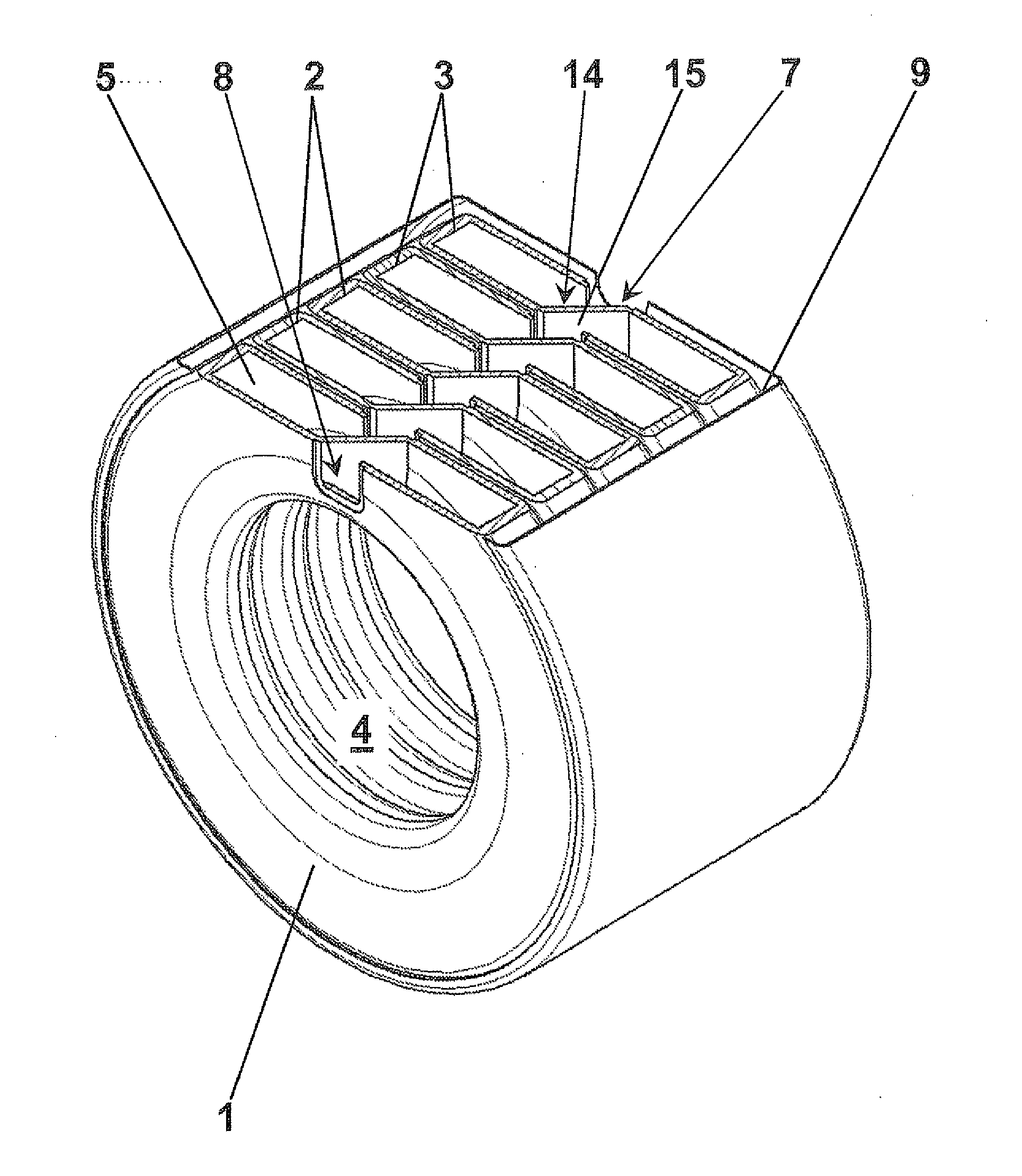
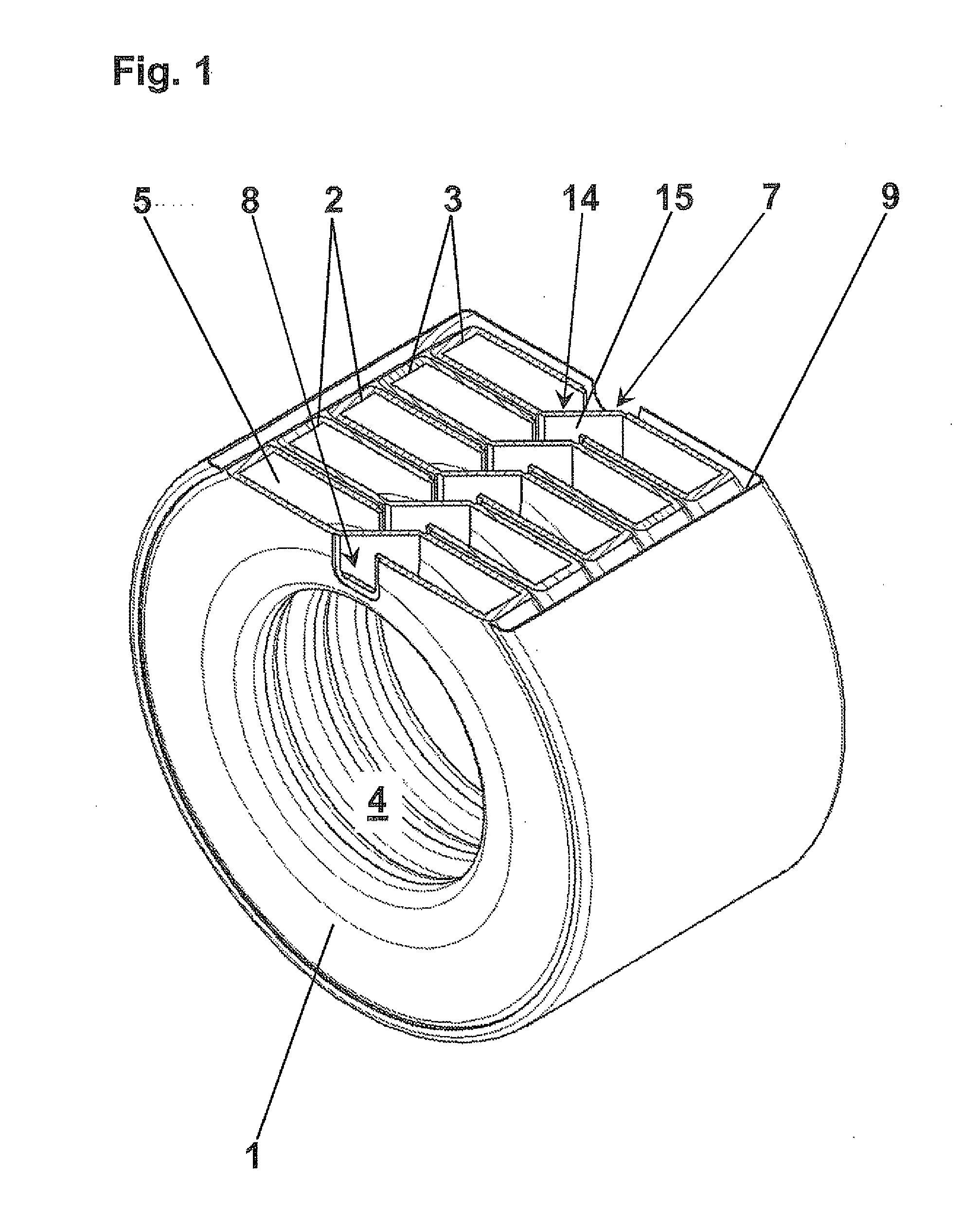
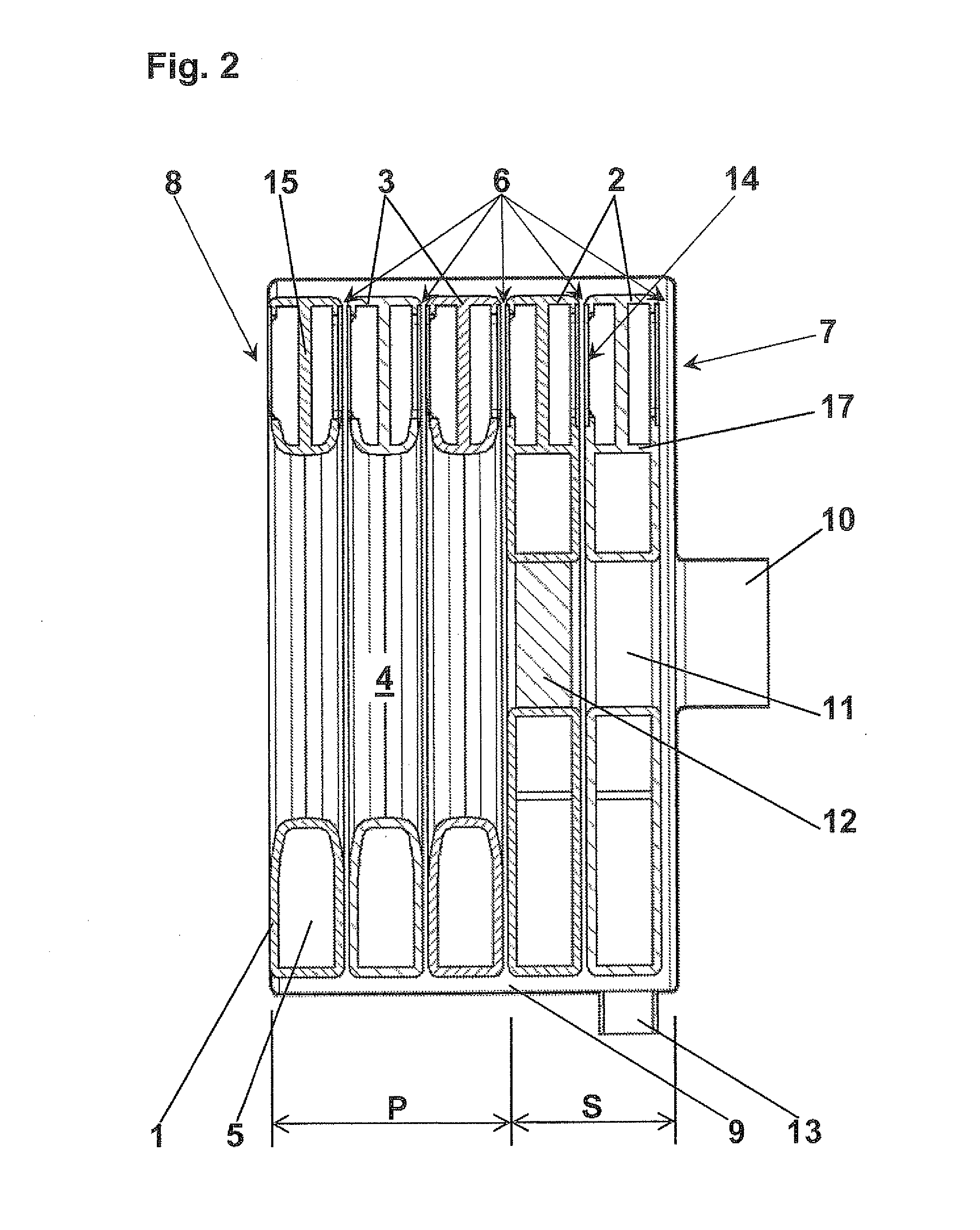
[0033]The sectional boiler is essentially made up of annular sections, namely, a front section 1, two rear section 2 and at least one center section 3. These form a combustion chamber 4 and their annular water chambers 5 are connected to one another.

[0034]The heat exchanger thus formed from a sectional block has gap-like heating gas flues 6, which extend approximately radially outward between two adjacent sections 1, 2, 3 having a mutually adapted geometry. Return port 7 and feed port 8 are located on opposite sides of the sectional block.

[0035]According to the exemplary embodiments and / or exemplary methods of the present invention, the heating gas flues are subdivided into a primary segment P and a secondary segment S. Front section 1 and at least one center section 3 thus belong on the water side and heating gas side to primary segment P, whereas the two rear sections 2 form secondary segment S.

[0036]Heating gas flues 6 run in primary segment P, respectively from combustion chambe...


PUM


Abstract

A sectional boiler is described as made of cast iron or aluminum, in particular a condensing boiler, having essential annular sections, a front section, at least one rear section and at least one center section being provided, which form a combustion chamber having an essentially surrounding heat exchanger made of a sectional block, whose annular water chambers are connected to one another and which has gap-like heating gas flues, which extend between two adjacent sections with a mutually adapted geometry approximately radially and empty into an exhaust gas collection chamber, and having a return port and a feed port. The present system is based on the objective of optimizing a sectional boiler made of cast iron or aluminum as a condensing boiler particularly with respect to compactness and robustness. The present system provides that the return port and the feed port are located on opposite sides of the sectional block, the flow passes through the water chambers of the sections in series starting from the return port, and the individual sections are respectively provided hydraulically with overflow openings in only one place on the periphery and are connected by these on at least one side with an adjacent section.

Description

FIELD OF THE INVENTION[0001]The present invention relates to a sectional boiler, in particular a condensing boiler made of cast iron or aluminum materials.BACKGROUND INFORMATION[0002]Sectional boilers of this kind are made up of multiple boiler sections cast in one piece, which are arranged one behind the other and are normally connected to one another on the water side by hubs. A flow is thus created through the water channels and water pockets formed by the boiler sections between the return port and the feed port. Normally, generic sectional boilers have a lower return port and a feed port situated on top, which may be in the respective hub. The heating gases flow from the combustion chamber via downstream heating gas flues to an exhaust gas connection and on their way give off heat to the boiler water.[0003]In all existing boilers of this kind, the sections are arranged in series one behind the other. There is an annular front section, on which a combustion chamber door or a bur...

Claims


Application Information

Patent Timeline
Patent Type & Authority Applications(United States)
IPC IPC(8): F22B7/00
CPCF24H1/43F24H1/445F24H8/00F24H9/0015F28D7/005Y02B30/102F28D7/026F28D9/0012F28D2021/0024F28F9/026F28D7/024Y02B30/00
Inventor RAUSCH, RAINER
Owner ROBERT BOSCH GMBH
Learn More