Semiconductor device
a technology of semiconductor devices and semiconductors, applied in semiconductor devices, digital storage, instruments, etc., can solve the problems of multi-level memory devices, increase in size and cost, etc., and achieve the effects of adequate power consumption, simplified circuit configuration, and extremely long storage tim
- Summary
- Abstract
- Description
- Claims
- Application Information
AI Technical Summary
Benefits of technology
Problems solved by technology
Method used
Image
Examples
embodiment 1
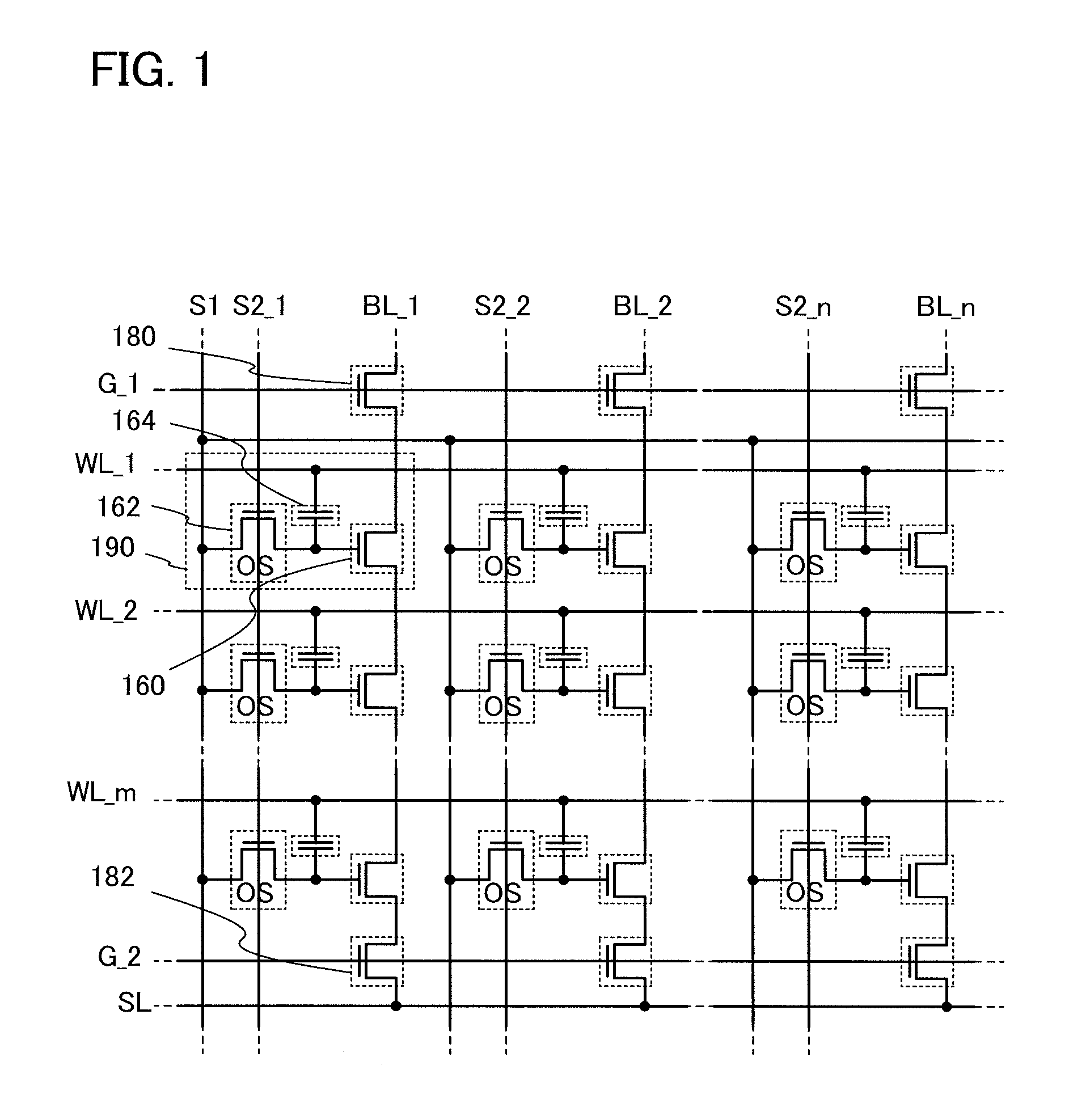
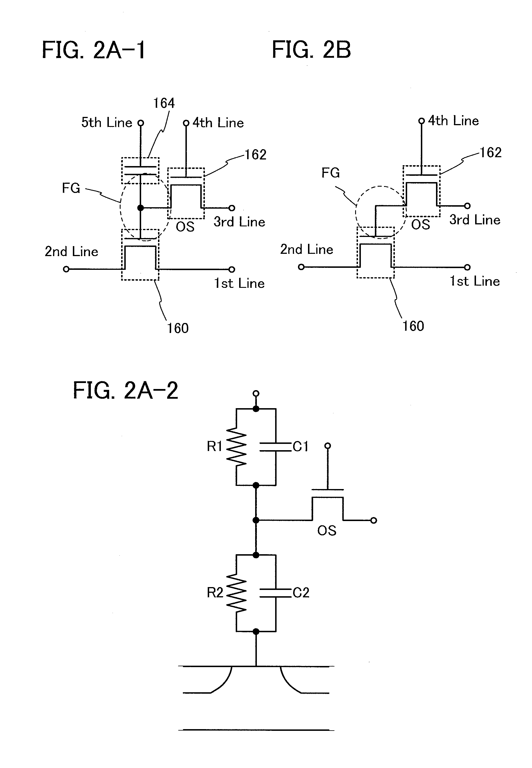
[0068]In this embodiment, a circuit configuration and an operation of a semiconductor device according to one embodiment of the disclosed invention will be described with reference to FIG. 1, FIGS. 2A-1, 2A-2, and 2B, FIG. 3, FIG. 4, FIG. 5, FIG. 6, FIG. 7, and FIG. 8. Note that in each of circuit diagrams, in some cases, “OS” is written beside a transistor in order to indicate that the transistor includes an oxide semiconductor.
[0069]In the semiconductor device in this embodiment, a signal line for controlling on / off of a writing transistor for conducting a writing operation on a memory cell is disposed along a bit line. Further, in the driving method of the semiconductor device, a multilevel writing operation is conducted with use of, also in a writing operation, a voltage which is applied to a capacitor at a reading operation.
[0070]First, a basic circuit configuration and its operation will be described with reference to FIGS. 2A-1, 2A-2, and 2B. In a semiconductor device illustr...
embodiment 2
[0130]In this embodiment, a structure and a manufacturing method of a semiconductor device according to one embodiment of the disclosed invention will be described with reference to FIG. 5 and FIGS. 9A and 9B, FIGS. 10A to 10D, FIGS. 11A to 11D, FIGS. 12A to 12D, and FIGS. 13A to 13C.
[0131]FIGS. 9A and 9B show an example of a structure of the memory cell 190 of the semiconductor device illustrated in the circuit diagram of FIG. 5. FIG. 9A illustrates a cross section of the semiconductor device, and FIG. 9B illustrates a plan view of the semiconductor device. Note that, in the plan view illustrated in FIG. 9B, the drawing is simplified without the insulating layer 154, the insulating layer 172, the wiring 171 and the wiring 158 illustrated. Here, in FIG. 9A, the direction parallel to the line A1-A2 of FIG. 9B corresponds to the column direction in the circuit diagram of FIG. 5, and the direction perpendicular to the line A1-A2 of FIG. 9B corresponds to the row direction in the circui...
embodiment 3
[0268]In this embodiment, an example of a transistor that can be applied to a semiconductor device disclosed in this specification will be described. There is no particular limitation on the structure of the transistor that can be applied to a semiconductor device disclosed in this specification; for example, a staggered type or a planar type having a top-gate structure or a bottom-gate structure can be employed. The transistor may have a single-gate structure in which one channel formation region is formed, a double-gate structure in which two channel formation regions are formed, or a triple-gate structure in which three channel formation regions are formed. Alternatively, the transistor may have a dual gate structure including two gate electrode layers positioned over and below a channel formation region with a gate insulating layer provided therebetween.
[0269]FIGS. 15A to 15D each illustrate an example of a cross-sectional structure of a transistor that can be applied to a semic...
PUM
 Abstract
Description
Claims
Application Information
 - R&D
- Intellectual Property
- Life Sciences
- Materials
- Tech Scout
- Unparalleled Data Quality
- Higher Quality Content
- 60% Fewer Hallucinations
Browse by: Latest US Patents, China's latest patents, Technical Efficacy Thesaurus, Application Domain, Technology Topic, Popular Technical Reports.
© 2025 PatSnap. All rights reserved.Legal|Privacy policy|Modern Slavery Act Transparency Statement|Sitemap|About US| Contact US: help@patsnap.com


