Gate driving circuit and liquid crystal display device having the same

Active Publication Date: 2012-01-05
LG DISPLAY CO LTD
View PDF8 Cites 9 Cited by
  • Summary
  • Abstract
  • Description
  • Claims
  • Application Information

AI Technical Summary

Benefits of technology

[0029]Therefore, to address such problems, an aspect of the detailed description is to provide a gate driving circuit capable of improving yield by ensuring a design margin and reducing a fabricating cost, and a liquid crystal display device having the same.
[0048]As described above, the gate driving circuit and a liquid crystal display device having the same can provide an effect of improving yield by ensuring a design margin and reducing a fabricating cost.

Problems solved by technology

However, the timing controller 40 of FIG. 1 does not separately provide a reset signal for resetting the N−1th stage and the Nth stage.
As such, upon employing the GIP type gate driving circuit of FIG. 2 and the GIP type bidirectional gate driving circuit of FIG. 4, the dummy shift resistor 23 and the first and second dummy gate driving units 53 and 55 should be respectively formed on the LC panel 10, which causes reduction of a design area and difficulty in ensuring a process margin, resulting in an increase in a fabricating cost of the LC panel 10.

Method used


Image

  • Gate driving circuit and liquid crystal display device having the same
  • Gate driving circuit and liquid crystal display device having the same
  • Gate driving circuit and liquid crystal display device having the same

Examples


Embodiment Construction

[0061]Description will now be given in detail of a GIP type LCD device in accordance with the exemplary embodiments, with reference to the accompanying drawings. For the sake of brief description with reference to the drawings, the same or equivalent components will be provided with the same reference numbers, and description thereof will not be repeated.

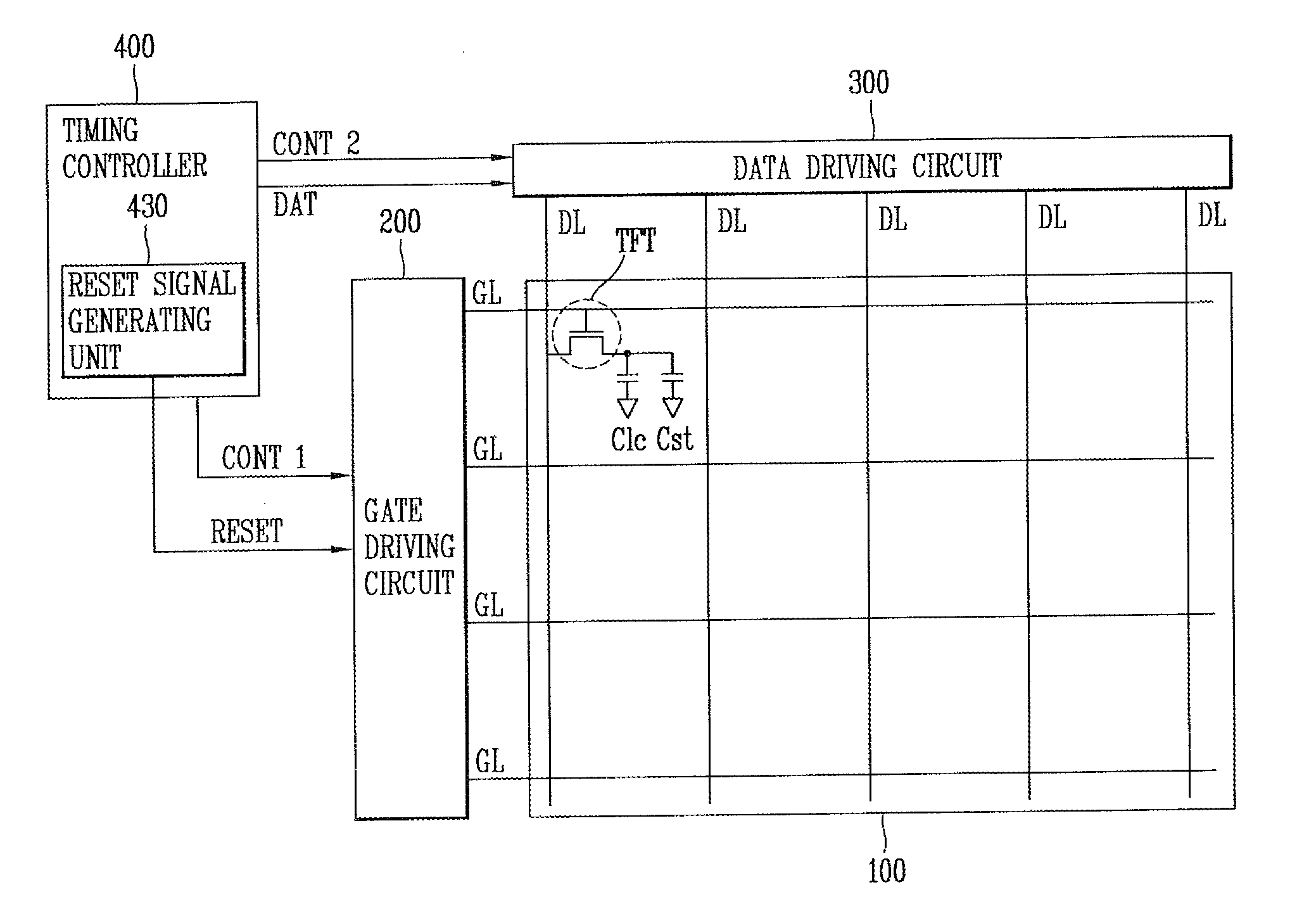
[0062]FIG. 5 shows a GIP type LCD device in accordance with one exemplary embodiment.

[0063]As shown in FIG. 5, the GIP type LCD device may include an LC panel 100, a gate driving circuit 200, a data driving circuit 300 and a timing controller 400.

[0064]The LC panel 100 may include a plurality of gate lines GL and a plurality of data lines DL, and a plurality of pixels connected to the gate and data lines GL and DL and aligned in a matrix configuration. Here, the gate lines GL may be formed in a horizontal direction, and the data lines DL may be formed in a vertical direction.

[0065]Each pixel may include a TFT connected to the gate l...


PUM


Abstract

A gate driving circuit is capable of improving yield by virtue of acquisition of a design margin and reduction of a fabricating cost. The gate driving circuit includes a shift resistor having N stages driven by a start signal and first to fourth clock signals output from the exterior, and an externally input reset signal is applied to reset terminals of the N−1th stage and the Nth stage of the shift resistor, respectively.

Description

CROSS-REFERENCE TO RELATED APPLICATION[0001]This application claims the benefit of Korean Patent Application No. 10-2010-0063620, filed on Jul. 1, 2010, which is hereby incorporated by reference for all purposes as if fully set forth herein.BACKGROUND OF THE INVENTION[0002]1. Field of the Invention[0003]This specification relates to a gate driving circuit, and particularly, to a gate driving circuit capable of improving yield by ensuring a design margin and reducing a fabricating cost, and a liquid crystal display device having the same.[0004]2. Background of the Invention[0005]In general, a liquid crystal display (LCD) device displays an image by adjusting light transmittance of liquid crystal (LC) having dielectric anisotrophy using an electric field.[0006]The LCD device includes a liquid crystal (LC) panel for displaying image data input from the exterior, and a driving circuit for driving the LC panel.[0007]Recently, an LCD device, which employs a Gate In Panel (GIP) type, in wh...

Claims


Application Information

Patent Timeline
IPC IPC(8): G09G3/36H03K3/00G09G5/00
CPCG09G3/3677G09G2300/0408G11C19/28G09G2310/08G09G2310/0286
Inventor KIM, YOUNG-DOCHA, JE-HEONLEE, HYUN-JEONG
Owner LG DISPLAY CO LTD
Why Eureka
Try Eureka