Fiber based milling device and method
a technology of fiber based milling and milling equipment, which is applied in the direction of solid separation, agriculture, chemistry apparatus and processes, etc., can solve the problems of increasing the cost of the device, and achieve the effect of high shear and cavitation levels and simple mechanical design
- Summary
- Abstract
- Description
- Claims
- Application Information
AI Technical Summary
Benefits of technology
Problems solved by technology
Method used
Image

Examples
example 1
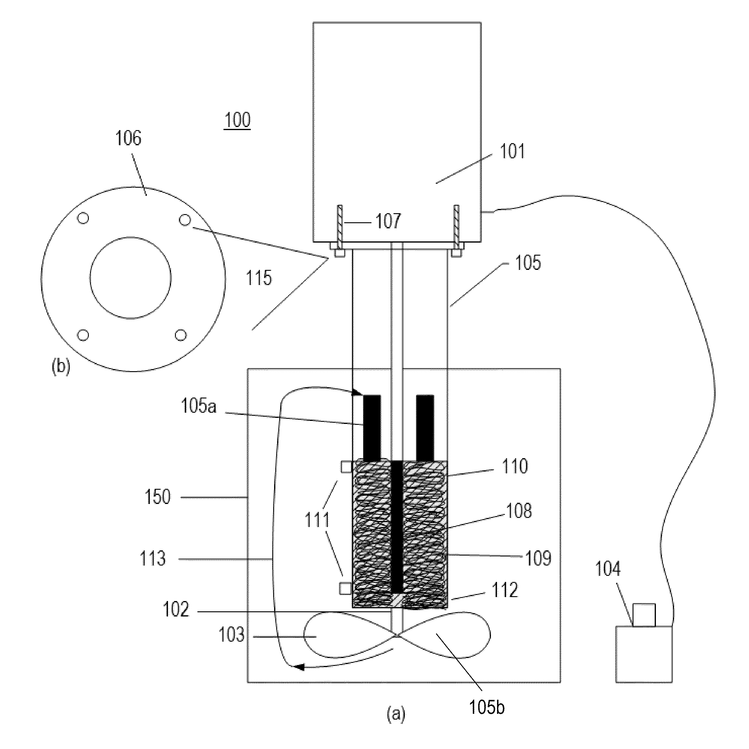
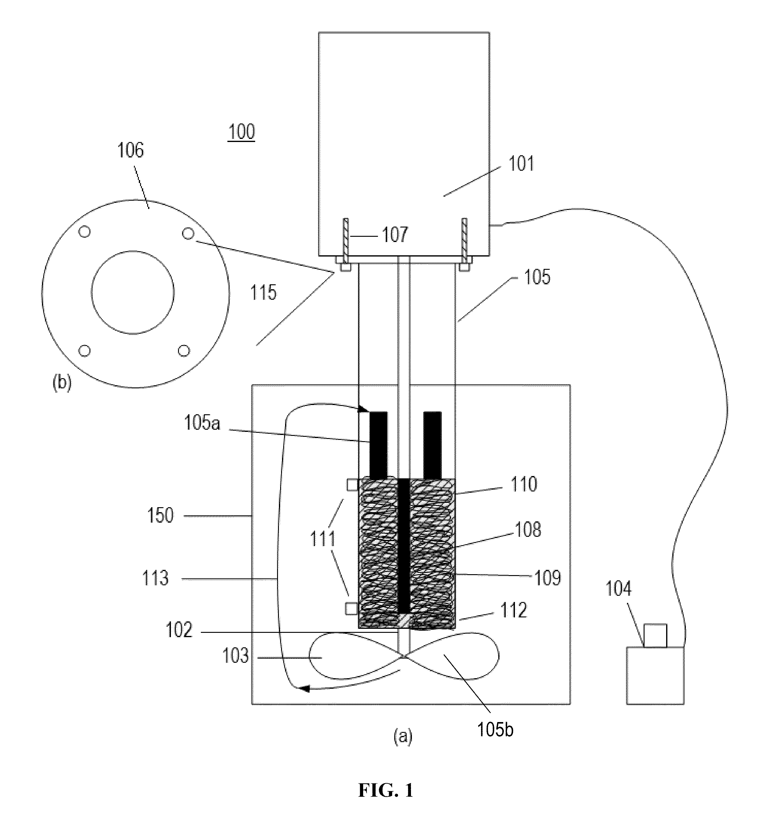
[0119]A cowles type disperser blade on a Premiere “Laboratory Dispersator” Model 2000 high speed disperser is replaced with an Indco MP153A laboratory impeller. A fiber laced rubber mat measuring 3 inches wide by 2.5 inches wide high is wrapped around the circumference of the ¾ inch diameter rotating shaft and affixed with standard plastic zipper type interlock ties. The fibers interlaced to the rubber mat are Vectran HT Fiber 2.5 denier filament yarn. The fibers are interlaced into the mat to maximize the density of the fiber arrangement. The fibers are woven in a loop pattern such that the loops reach within 1 / 16 of an inch of the pipe mixing chamber.
[0120]The disperser shaft with fibers attached thereto is encapsulated in a cylindrical pipe arrangement surrounded by a 3 inch tall section of 304 stainless steel wire 0140 mesh (30 mesh per linear inch) cloth. The bottom of the mesh cylinder is supported by a thin stainless steel ring cut from a length of 1.5 inch 304 stainless stee...
example 2
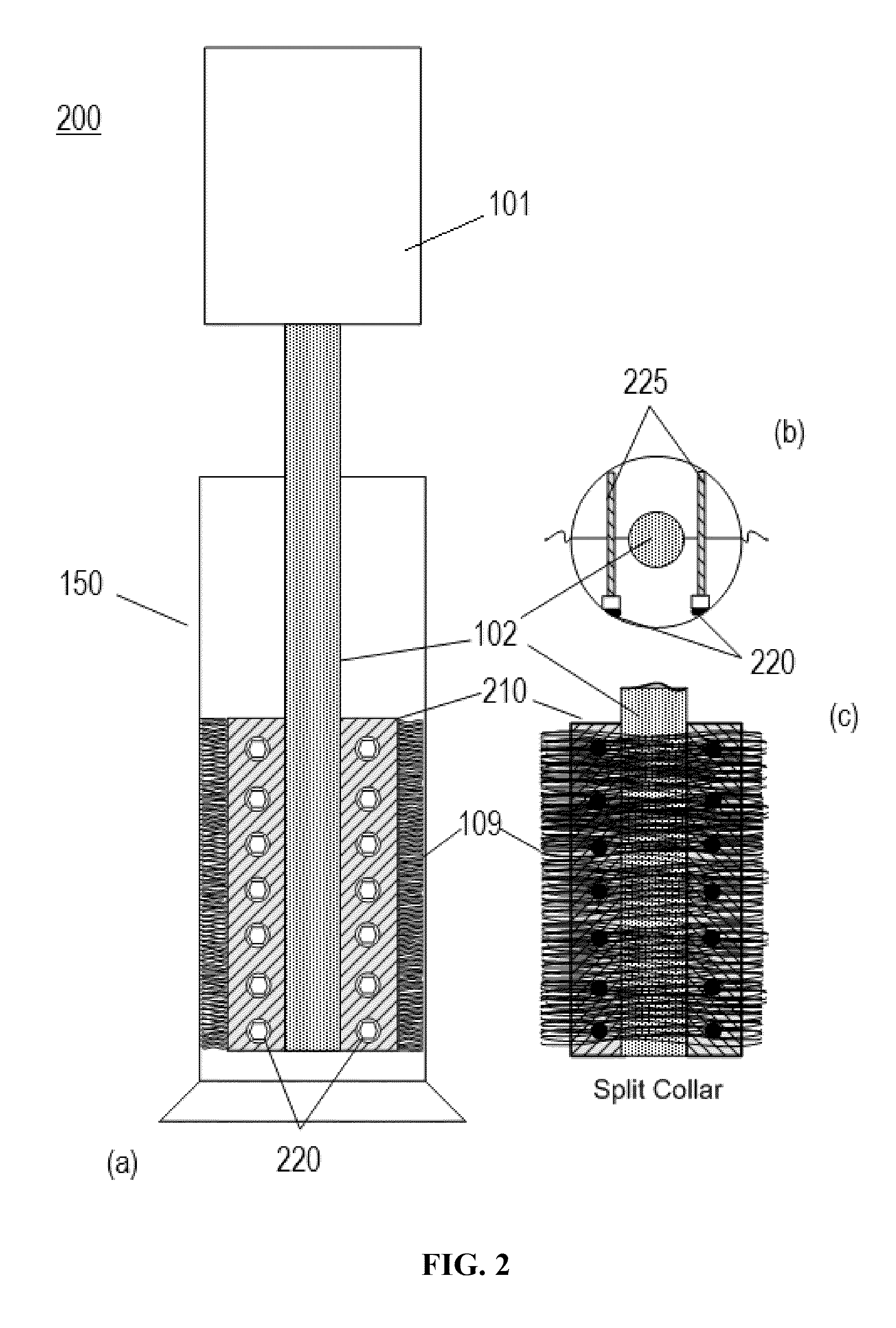
[0122]The Premiere disperser shaft is fitted with a custom made 316 stainless steel shaft collar measuring 3.5 in. high and 1⅝ in. in diameter. Preferably, the shaft collar is cut in two equal halves in the direction of the axis of the disperser shaft. The collar can be rejoined along its length by a vertical series of custom tapped and beveled points to accommodate seven 1¼ in. machine screws on both sides.
[0123]Inside the halved shaft collars is placed a high density of the Vectran fibers described above. The fibers are cut to a length of 2⅛ in. This will place the fiber end within 1 / 16 in. of the milling chamber wall. The fibers are held in place with a small amount of temporary adhesive. For example, two side adhesive transparent tape can be used. The collar halves are re-joined such that the collar bottom aligns with the bottom of the ¾ in. disperser shaft.
[0124]The above mentioned components are lowered into a standard plastic laboratory 500 milliliter graduated cylinder measu...
example 3
[0125]The Premiere “Laboratory Disperator” Model 2000 ¾ in. disperser shaft is adapted with circular cuts of 304 stainless steel perforated plate. The plate is manufactured by the McNichols Company of Tampa, Fla. and is commercially available in 18 gauge thickness with 1 / 16 in. diameter perforations. The plates are spaced ⅛ in. apart. This plate is custom cut into two 1⅜ in. diameter circles. Vectran HT 2.5 denier filament yarn fibers as supplied by Engineered Fibers Technology of Shelton, Conn. are woven between the plates such that the distance between the plates is 2¼ in. The perforated plate is fitted to the disperser shaft and secured with standard snap rings below the top plate and above the bottom plate such that the vertical fibers are immobilized relative to the vertical length of the disperser shaft. The fiber / plate arrangement is situated such that the bottom perforated plate aligns with the bottom of the disperser shaft.
[0126]A primary construction feature of the pipe co...
PUM
 Abstract
Description
Claims
Application Information
 - R&D
- Intellectual Property
- Life Sciences
- Materials
- Tech Scout
- Unparalleled Data Quality
- Higher Quality Content
- 60% Fewer Hallucinations
Browse by: Latest US Patents, China's latest patents, Technical Efficacy Thesaurus, Application Domain, Technology Topic, Popular Technical Reports.
© 2025 PatSnap. All rights reserved.Legal|Privacy policy|Modern Slavery Act Transparency Statement|Sitemap|About US| Contact US: help@patsnap.com