Optical fiber

a technology of optical fiber and fiber, applied in the field of optical fiber, can solve the problems of inability to easily transmit a large amount of information, loss of transmission, exponential fashion, etc., and achieve the effect of wide transmission band and improved bending characteristics

Active Publication Date: 2011-11-24
SHIN ETSU CHEM IND CO LTD
View PDF2 Cites 2 Cited by
  • Summary
  • Abstract
  • Description
  • Claims
  • Application Information

AI Technical Summary

Benefits of technology

[0016]In view of the above-described prior art, the present invention aims to provide an optical fiber having MFD conforming to G652 standard (preferably 9 μm or above), improved bending characteristics, as well as providing an optical fiber having a sufficiently wide transmission band in multimode transmission in the 850 nm band, in view of application to a light source in the 850 nm band.

Problems solved by technology

Such electric cables, however, have a narrow band and so are easily affected by the electromagnetic wave noise, and so cannot easily transmit a large amount of information.
This is because if optical fibers widely different in MFD are connected to each other, it would cause transmission loss.
However as the bending radius becomes small, the ratio of leak of unpropagated light from the core increases in an exponential fashion, to cause transmission loss.
However, connection loss is large when an optical fiber having MFD of about 6 μm is connected to an optical fiber having MFD of about 10 μm, and so the main line and the user line should operate in single mode optical fiber systems separate from each other.
Laser optical sources and optical receivers used in the wavelength of 1300 nm band are comparatively expensive, and so cheaper light emitting diodes (LED) and a surface emitting lasers (VCSEL) in the 850 nm band are often used.

Method used


Image

  • Optical fiber
  • Optical fiber
  • Optical fiber

Examples


embodiment examples

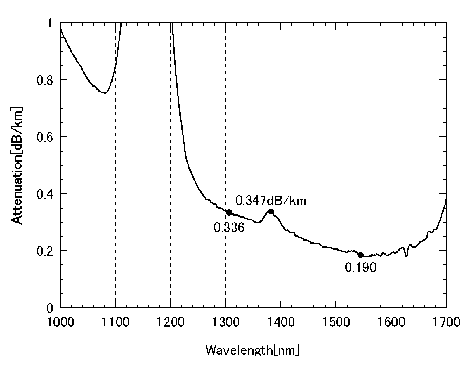
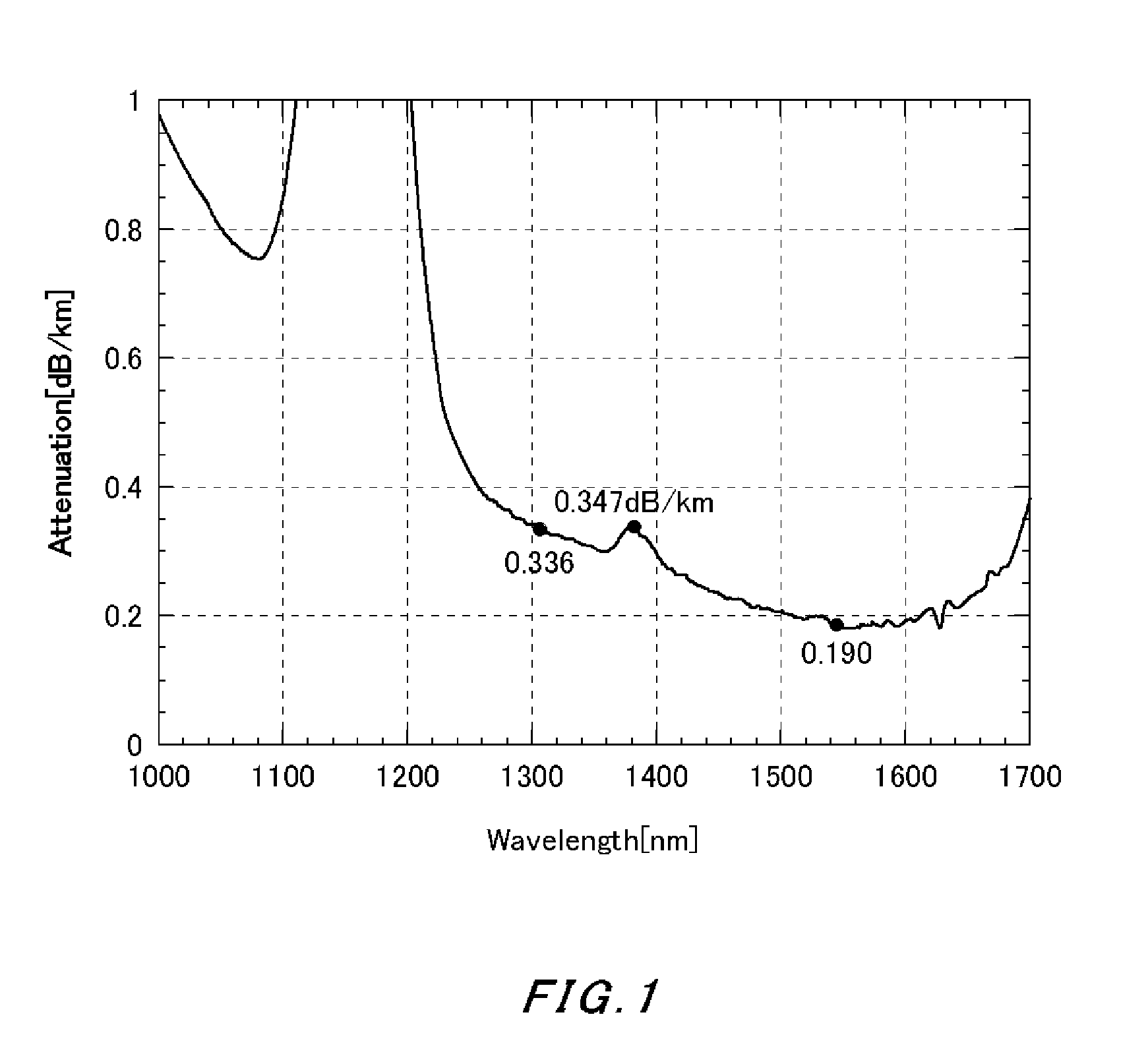
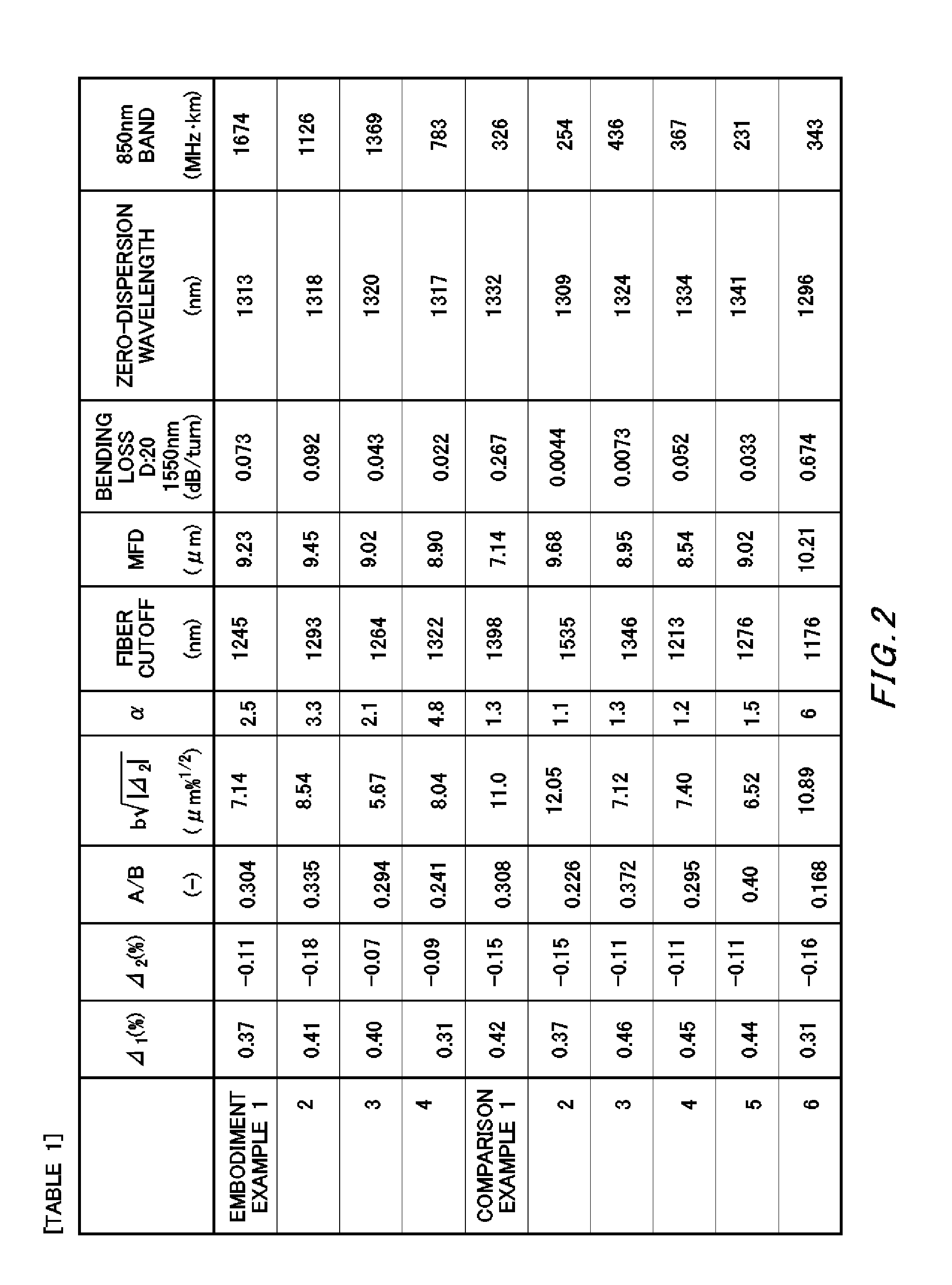
[0028]In Embodiment Example 1, the numerical value for each parameter for a desirable optical fiber is set first, and material supply conditions and deposition conditions are appropriately set in accordance with the numerical values. Then, a VAD method is used to manufacture a core material having a core region and a first cladding adjacent to the core and covering a circumference of the core. After stretching the core material into a desirable diameter, a second cladding is formed at an exterior of it. Thus obtained glass base material is drawn to have a cladding diameter of 125 μm. Then, the circumference of the cladding is coated with urethane acrylate, thereby obtaining an optical fiber wire having a length of 250 mm. Each parameter of the optical fiber manufactured in the above manner is as follows.

(1) the specific refractive index difference Δ1 of the maximum of the refractive index distribution of the core: 0.37(%)

(2) the specific refractive index difference Δ2 from the minim...


PUM


Abstract

Provided is an optical fiber including: a core at a center thereof; a first cladding adjacent to the core to cover a circumference of the core; and a second cladding adjacent to the first cladding to cover a circumference of the first cladding, where 0.35%≦(Δ1−Δ2)≦0.65%, 0.30%≦Δ1≦0.55%, −0.20%≦Δ2≦−0.05%, 0.22≦a/b≦0.34, and 4≦b√|Δ2|≦10 hold, and loss increase resulting when the optical fiber is wound on a mandrel having a diameter of 20 mm is 0.5 dB/turn or smaller at a wavelength of 1550 nm, where Δ1(%) is a specific refractive index difference of a maximum of a refractive index distribution of the core with reference to a refractive index of the second cladding, Δ2(%) is a specific refractive index difference of a minimum of a refractive index distribution of the first cladding with reference to the refractive index of the second cladding, a(μm) is a radius of a boundary between the core and the first cladding with respect to a center of the core, and b(μm) is a radius of a boundary between the first cladding and the second cladding with respect to the center of the core.

Description

[0001]The contents of the following patent application is incorporated herein by reference, No. 2009-121938 filed on May 20, 2009.BACKGROUND[0002]1. Technical Field[0003]The present invention relates to an optical fiber for optical communication, and particularly relates to an optical fiber suitable as a long distance line and Optical Fiber To The Home (FTTH) having transmission length of some tens of kilometers, and interconnection inside or outside homes in local area networks (LAN).[0004]2. Related Art[0005]Optical fibers are suitable for long distance communication for their wide band characteristics, and are widely used for communication in main lines of a long distance such as some tens of kilometers and above.[0006]On the other hand, with rapid prevalence of the Internet, the amount of information transceived by individual personal computers has also increased dramatically. The widely used technology in this field has been copper electric cables such as a coaxial cable and an...

Claims


Application Information

Patent Timeline
Patent Type & Authority Applications(United States)
IPC IPC(8): G02B6/036
CPCG02B6/03627G02B6/0281
Inventor OYAMADA, HIROSHIURATA, YUHEI
Owner SHIN ETSU CHEM IND CO LTD
Why Eureka
Try Eureka