Automatic coffee maker with sensor for detecting the quantity of coffee in the machine

a coffee maker and sensor technology, applied in the field of coffee machines, can solve the problems of increasing the cost and the size of the machine, the need of signalling, and the failure of the volumetric measurer,

Active Publication Date: 2011-11-24
VERSUNI HLDG BV
View PDF9 Cites 17 Cited by
  • Summary
  • Abstract
  • Description
  • Claims
  • Application Information

AI Technical Summary

Benefits of technology

[0019]In some embodiments, the sensor can provide at least an electrically conductive strip placed onto the outer surface of the container, which develops for an adequate length in a direction corresponding to the direction along thereof the level of coffee beans inside the container lowers. In this way it is possible obtaining an analog or digital signal which provides not only an alarm when the coffee goes below a minimum threshold or minimum level beyond thereof it is necessary to restore the quantity of coffee in the container, but even an indication about the really present level of coffee. Practically, in this way it is possible indicating the user through the interface the quantity of residual coffee, so that the user has more detailed information about the real level of coffee in the container. He / she can then realize the quantity of coffee even when this is abundantly above the level beyond thereof the machine has to be filled up again . This can be particularly useful, for example, to allow the user to programme the purchase of a new coffee pack.

Problems solved by technology

One of the problem arising in the modern coffee machines is the need of signalling the user the lack of coffee, in particular the lack of coffee beans in a reservoir upstream the grinder.
First of all it is necessary to adopt a system for measuring the quantity of ground coffee, which increases considerably the costs and the size of the machine.
Secondly, the volumetric measurer is subjected to failures and thus it represents a critical element in the operation of the machine.
This makes not very comfortable the use of the machine.
However, in this way when the container of coffee beans empties during the grinding of a coffee charge before the grinder has performed the revolutions corresponding to the coffee dose to be ground, the grinder continues to rotate without coffee therefore without producing powder and the machine is stopped after a certain period of time.
In each case, when the grinder has stopped, the central unit cannot recognize the already ground quantity of coffee and therefore it cannot know how much coffee should still be ground after the user has filled up again the container with beans.
This involves the clear drawback of wasting a partial coffee dose for each interruption due to the exhaustion of the beans in the container.
These optical systems have considerable drawbacks due to the fact that the environment wherein they have to work involves the deposit of coffee powders or debris preventing the used photocells or optical sensors from operating correctly.
Furthermore, the system is particularly expensive as it requires two components to be applied onto the container (a sender and a receiver).
Furthermore, it is necessary arranging the sensors inside the walls of the container or manufacturing the walls of the container with transparent material which, however, is likely to get dirty or wear out until preventing the sensors from operating correctly.
Furthermore, as it is known, the coffee beans can have difficulties in sliding inside the container and form bridges or blocks of beans which remain temporarily still.
If this happens under a condition of poor quantity of coffee contained in the container and locking the beam along the path from the sender to the receiver, the device does not operate and it does not send the signal of lack of coffee, even when the quantity of coffee in the container is insufficient for preparing one dose of drink.
A capacitive sensor is associated to the reservoir of coffee beans, which sensor should be useful to signal to the user the presence of coffee beans and consequently the lack of beans, but it is not able to provide information useful for handling more correctly the content of the reservoir of coffee beans.

Method used


Image

  • Automatic coffee maker with sensor for detecting the quantity of coffee in the machine
  • Automatic coffee maker with sensor for detecting the quantity of coffee in the machine
  • Automatic coffee maker with sensor for detecting the quantity of coffee in the machine

Examples


Embodiment Construction

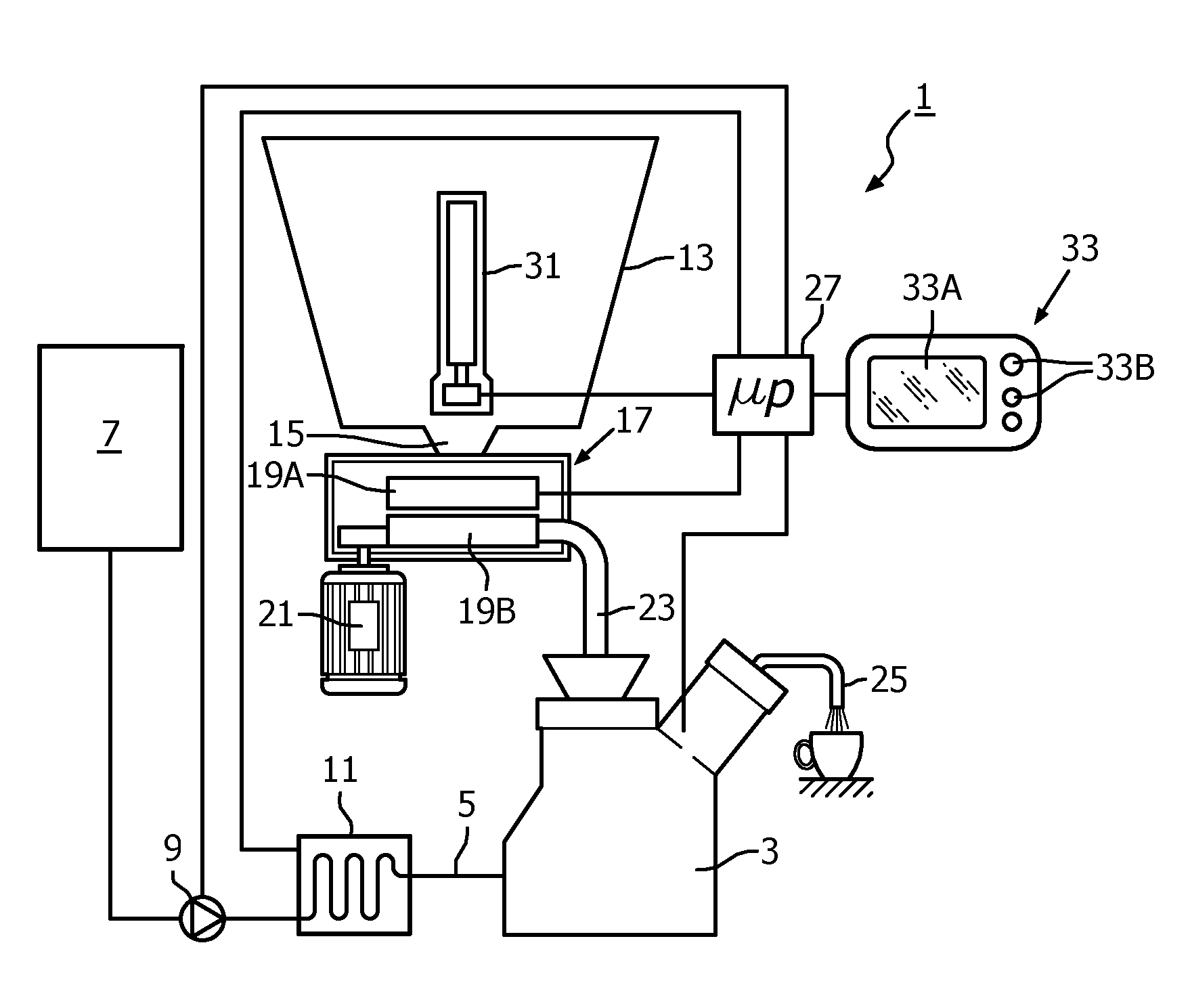
[0031]In FIG. 1 the main components of an automatic coffee machine, thereto the present invention can be applied, are represented under the form of functional blocks. The representation of the several blocks is schematic, as they are known to the person skilled in the art. The representation of FIG. 1 is to be meant exclusively as an example, as the invention can be implemented in machines of various type, even for example without the grinder unit, as indicated above.

[0032]By referring to FIG. 1, the machine, designated as a whole with 1, includes a brewing unit 3, thereto, by means of a line 5, hot water under pressure is supplied. The water is picked up from a reservoir 7 through a pump 9 which makes the water picked up from the reservoir 7 to flow through a boiler 11. This is represented as boiler with instantaneous heating, that is wherein the cold water pumped from the pump 9 is heated during the boiler crossing. Therefore the boiler 11 can also be of other type, for example an...


PUM


Abstract

The machine comprises: a brewing unit (3); a water reservoir (7); a boiler (11) for the production of hot water to supply to the brewing unit; a coffee container (13); an electronic control unit (27); a user interface (33). At least one capacitive sensor (31) is associated to the coffee container to detect the quantity of residual coffee in the container (13). The sensor is connected to the electronic control unit, which is programmed to supply to a user by means of the interface at least a piece of information regarding the quantity of coffee in said container.

Description

FIELD OF THE INVENTION[0001]The present invention relates to the field of the coffee machines, both for domestic use and professional use and in particular the field of the automatic or semi-automatic coffee machines.BACKGROUND OF THE INVENTION[0002]For producing coffee-based drinks semi-automatic or automatic machines are used with a high number of functions and controls. A high level of automation is applied also to the machines for domestic use and not only professional use. Typically a coffee machine has a brewing unit, a water reservoir , a boiler for the production of hot water to supply to the brewing unit, a coffee container, an electronic control unit and a user interface. By means of the interface, the user can set a series of functions, parameters for producing the drink and other, depending upon the machine model and the performances thereof. In some cases the machine produces exclusively coffee, whereas in others it can produce even other drinks, for example hot water, ...

Claims


Application Information

Patent Timeline
Patent Type & Authority Applications(United States)
IPC IPC(8): A47J31/44
CPCA47J31/42
Inventor POZZARI, STEFANOPILONE, CIRO ADELMO
Owner VERSUNI HLDG BV
Why Eureka
Try Eureka