
Inspection device and inspection method for boiler furnace water wall tubes

a technology of inspection device and inspection method, which is applied in the direction of material analysis through optical means, instruments, lighting and heating apparatus, etc., can solve the problems of reducing atmosphere, reducing temperature in the boiler furnace, and corrosion of boiler components such as water wall tubes, so as to reduce measurement errors, reduce wall thickness, and perform accurately

Active Publication Date: 2011-11-17
MITSUBISHI POWER LTD
View PDF1 Cites 22 Cited by
  • Summary
  • Abstract
  • Description
  • Claims
  • Application Information

AI Technical Summary

Benefits of technology

[0013]In view of such a conventional technical problem, it is an object of the present invention to provide an inspection device and an inspection method for boiler furnace water wall tubes, which can inspect reduced wall thickness conditions of multiple water wall tubes, extending in an up-down direction (vertical direction) along inner wall surfaces of a boiler furnace and arranged adjacent to each other, accurately and efficiently over a wide range based on surface shapes of the water wall tubes measured by a laser displacement sensor.
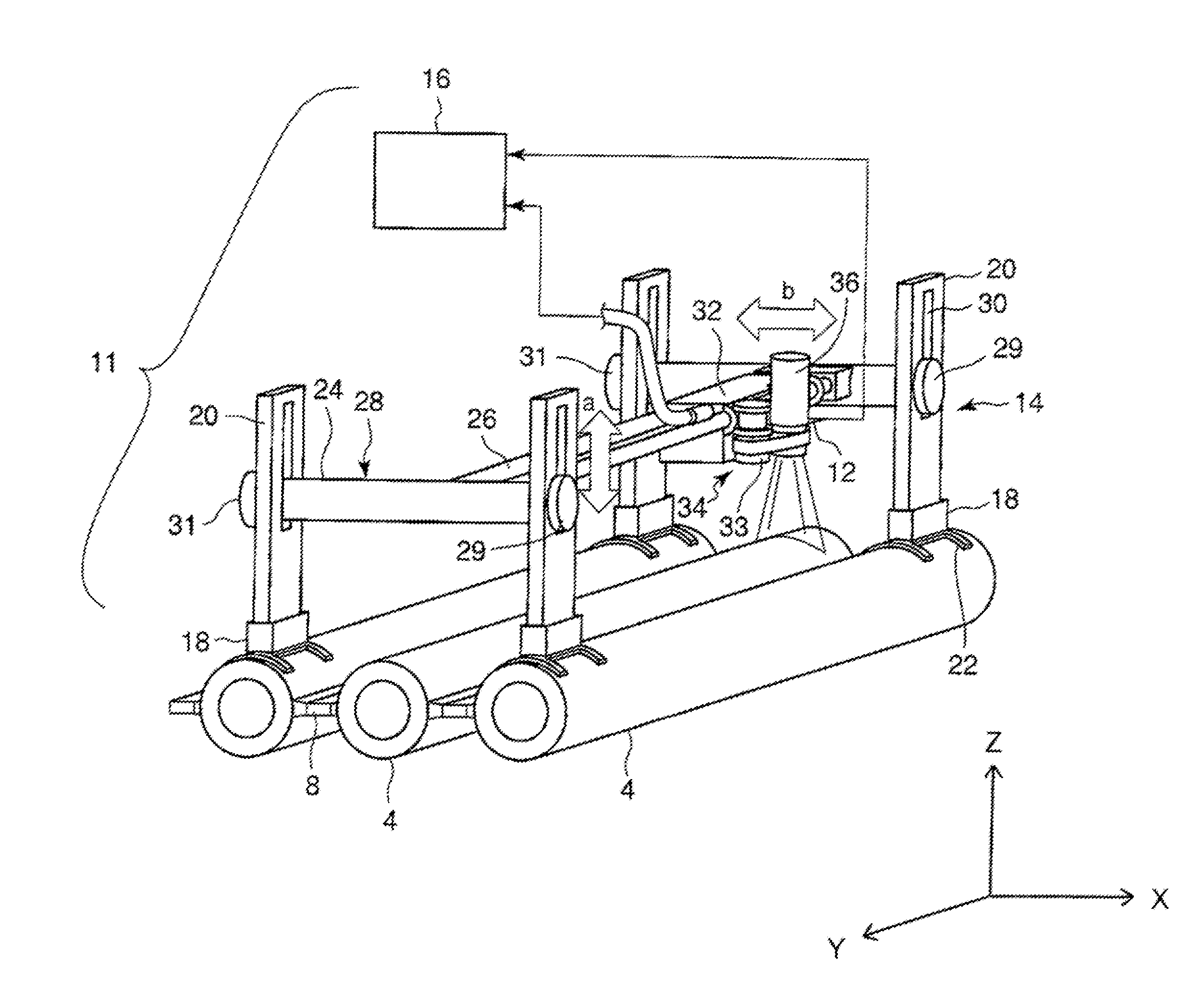
[0014]In order to solve such a problem, a first invention provides an inspection device for boiler furnace water wall tubes, which inspects reduced wall conditions of multiple water wall tubes extending in a vertical direction along inner wall surfaces of a boiler furnace and arranged adjacent to each other, characterized by comprising: a leg placed upright and fixed by a magnet onto the surface of a water wall tube; a support frame fixed to the leg to support a displacement sensor producing laser light to be irradiated onto the surface of the water wall tube; a moving mechanism for moving the displacement sensor in the axial direction of the water wall tube relative to the support frame; and reduced wall thickness evaluating means for measuring the surface shape of the water wall tube along a direction substantially perpendicular to the axial direction of the water wall tube based on a signal from the displacement sensor to calculate the amount of reduced wall thickness of the water wall tube from a difference between the measurement result of the surface shape and a reference shape without reduction in wall thickness in order to evaluate a reduced wall thickness condition.

Problems solved by technology

However, two-stage combustion makes the combustion atmosphere in a boiler furnace more reducing, causing a problem of corrosion of boiler components such as water wall tubes.
The problem with the boiler furnace water wall tubes today is sulfidation corrosion due to a reducing atmosphere.
Since this corrosion causes damage over a wide range in the furnace, it requires a lot of time and labor to identify the corrosion.
However, since the area to be inspected is large, it takes time and labor to inspect the area.
Further, visual inspection is affected by the inspector's subjective view, and there is a problem that the results vary widely.
The ultrasonic thickness measurement is quantitatively reliable, but since it is a point measurement to measure wall thickness at a fixed point, it is not suitable for measuring general corrosion conditions of water wall tubes.

Method used


Image

  • Inspection device and inspection method for boiler furnace water wall tubes
  • Inspection device and inspection method for boiler furnace water wall tubes
  • Inspection device and inspection method for boiler furnace water wall tubes

Examples


Embodiment Construction

[0051]The present invention will be described in detail below with reference to an embodiment shown in the drawings. Note that the size, material, shape, and relative position of components described in the embodiment do not limit the scope of this invention unless otherwise particularly mentioned, and the embodiment is just illustrative example.

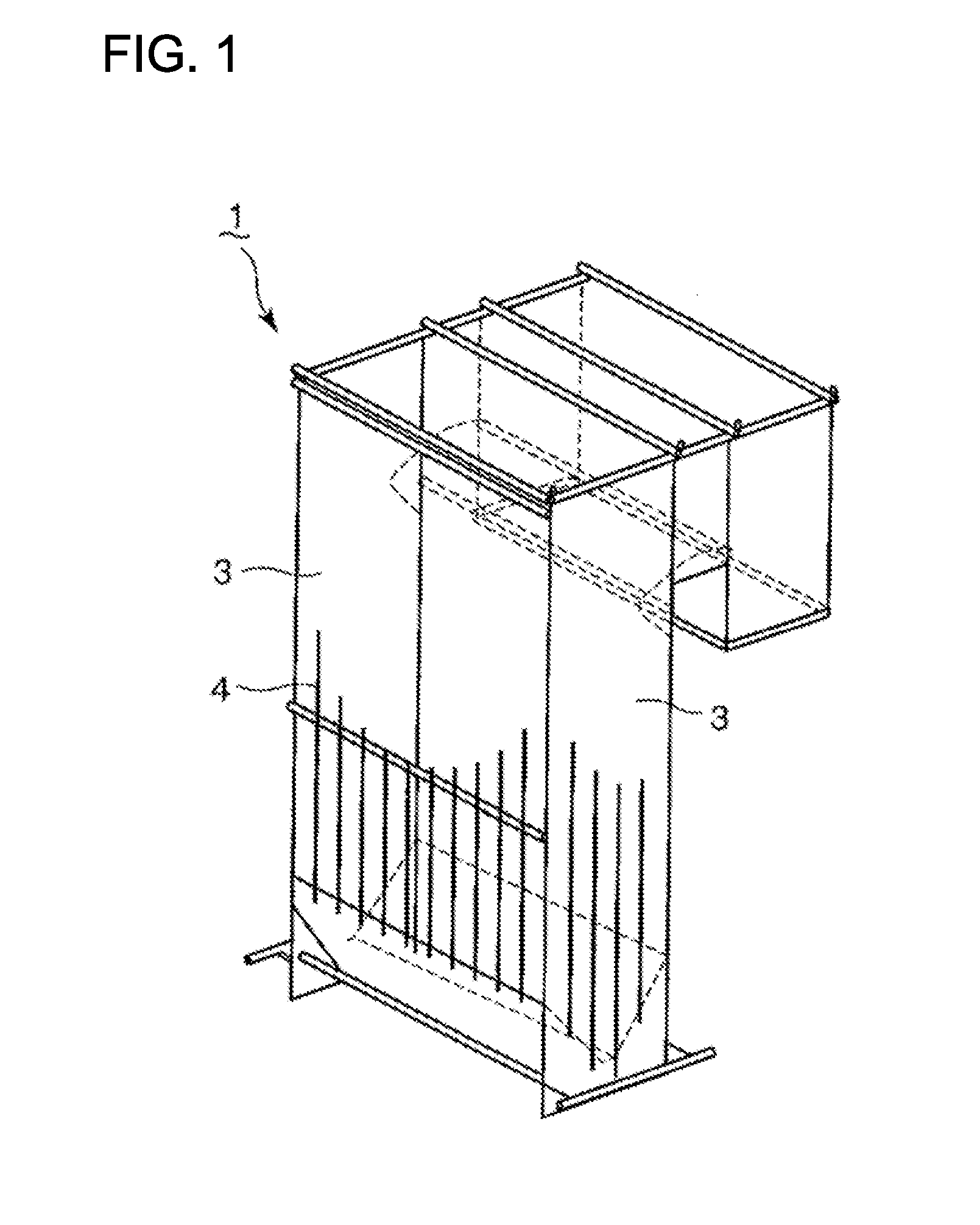
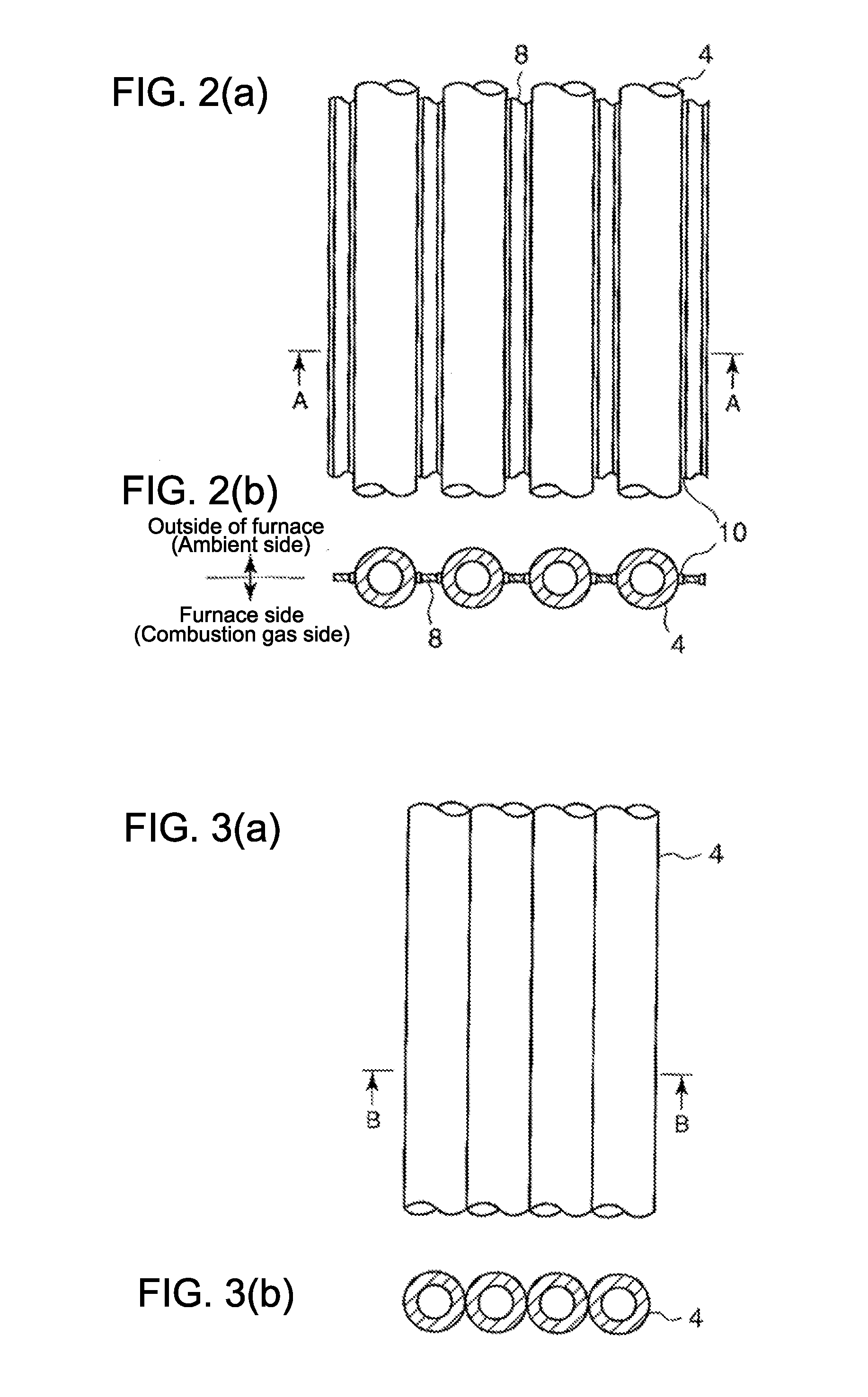
[0052]A boiler schematic diagram is shown in FIG. 1. A boiler furnace 1 is constructed of four water walls 3 the inside of which is burned by a burner. Inside the water walls 3, multiple water wall tubes 4 extend in an up-down direction (vertical direction) and are arranged adjacent to each other by welding or in contact with each other. Alternatively, the water walls 3 themselves may be made up of the multiple water wall tubes 4 extending in the up-down direction (vertical direction) and welded adjacent to each other. Then, water is poured into the water wall tubes 4 and heated therein to produce steam. For the water wall tubes 4, there are...


PUM


Abstract

There are provided an inspection device and an inspection method for boiler furnace water wall tubes, which can inspect reduced wall thickness conditions of multiple water wall tubes, extending in an up-down direction along inner wall surfaces of a boiler furnace and arranged adjacent to each other, accurately and efficiently over a wide range based on surface shapes of the water wall tubes measured by a laser displacement sensor. A scanner 14 including columns 20 placed upright and fixed by magnets onto the surfaces of multiple water wall tubes 4 extending the up-down direction on the inner wall surfaces of the boiler furnace, a support frame 28 fixed to the columns 20 to support a displacement sensor 12 producing laser light to be irradiated onto the surface of a water wall tube 4, and a moving mechanism 31 for moving the displacement sensor 12 in the axial direction of the water wall tube 4 relative to the support frame 28. A signal processing unit 16 is also provided for calculating the amount of reduced wall thickness of the water wall tube 4 from a difference between the cross-sectional surface shape of the water wall tube 4 based on a signal from the displacement sensor 12 and a reference shape without reduction in wall thickness in order to evaluate a reduced wall thickness condition.

Description

TECHNICAL FIELD[0001]The present invention relates to an inspection device and an inspection method for boiler furnace water wall tubes, and particularly to an inspection device and an inspection method for measuring the surface geometry of a water wall tube arranged in a boiler furnace using a non-contact sensor to evaluate the degree of corrosion of the water wall tube based on the measured value.BACKGROUND ART[0002]Due to the recent serious environmental problem, land boilers for power generation are required to reduce NOx in flue gas, and measures are often taken from the viewpoint of combustion technology, such as two-stage combustion with relatively low cost.[0003]However, two-stage combustion makes the combustion atmosphere in a boiler furnace more reducing, causing a problem of corrosion of boiler components such as water wall tubes. The problem with the boiler furnace water wall tubes today is sulfidation corrosion due to a reducing atmosphere. Since this corrosion causes d...

Claims


Application Information

Patent Timeline
IPC IPC(8): G01B11/06
CPCF22B37/005G01N21/952G01B11/06
Inventor MATSUMOTO, HIROTOSHIIDA, KEIJIMURATA, HIDEAKIZHANG, KAI
Owner MITSUBISHI POWER LTD
Learn More