
Complementary spin transistor logic circuit

a logic circuit and complementary spin technology, applied in the field of logic circuits, can solve the problems of large cost and limitation of known silicon-based complementary mos technology, and achieve the effect of fast processing and low power consumption

Active Publication Date: 2011-11-17
KOREA INST OF SCI & TECH
View PDF0 Cites 26 Cited by
  • Summary
  • Abstract
  • Description
  • Claims
  • Application Information

AI Technical Summary

Benefits of technology

The present invention provides a complementary spin transistor logic circuit with low power consumption, fast processing, nonvolatility, and multi-switching characteristics. The circuit can perform a memory function and is suitable for use in a multifunctional logic circuit. The circuit includes a parallel spin transistor and an anti-parallel spin transistor, which are connected to a common input terminal. The transistors are made of ferromagnetic materials or magnetic semiconductors and are connected to a drain and a source through a channel layer. The circuit can perform various operations and is suitable for use in a variety of applications.

Problems solved by technology

The known silicon-based complementary MOS (CMOS) technology has a limitation in that size reduction needs a lot of cost.

Method used


Image

  • Complementary spin transistor logic circuit
  • Complementary spin transistor logic circuit
  • Complementary spin transistor logic circuit

Examples


Embodiment Construction

[0035]Exemplary embodiments of the present invention will now be described in detail with reference to the accompanying drawings. However, it should be noted that the spirit of the present invention is not limited to the embodiments set forth herein and those skilled in the art and understanding the present invention can easily accomplish retrogressive inventions or other embodiments included in the spirit of the present invention by the addition, modification, and removal of components within the same spirit, and those are to be construed as being included in the spirit of the present invention.

[0036]Further, throughout the drawings, the same or similar reference numerals will be used to designate the same components or like components having the same functions in the scope of the similar idea.

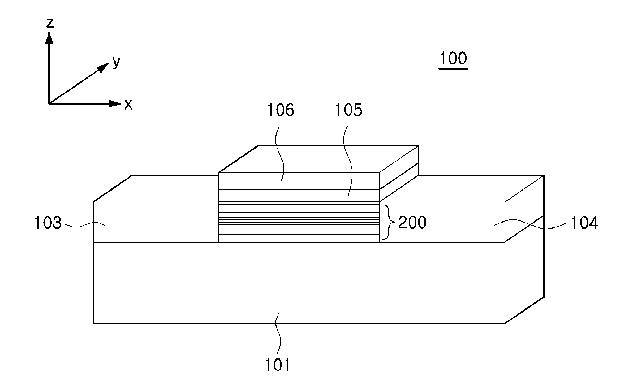
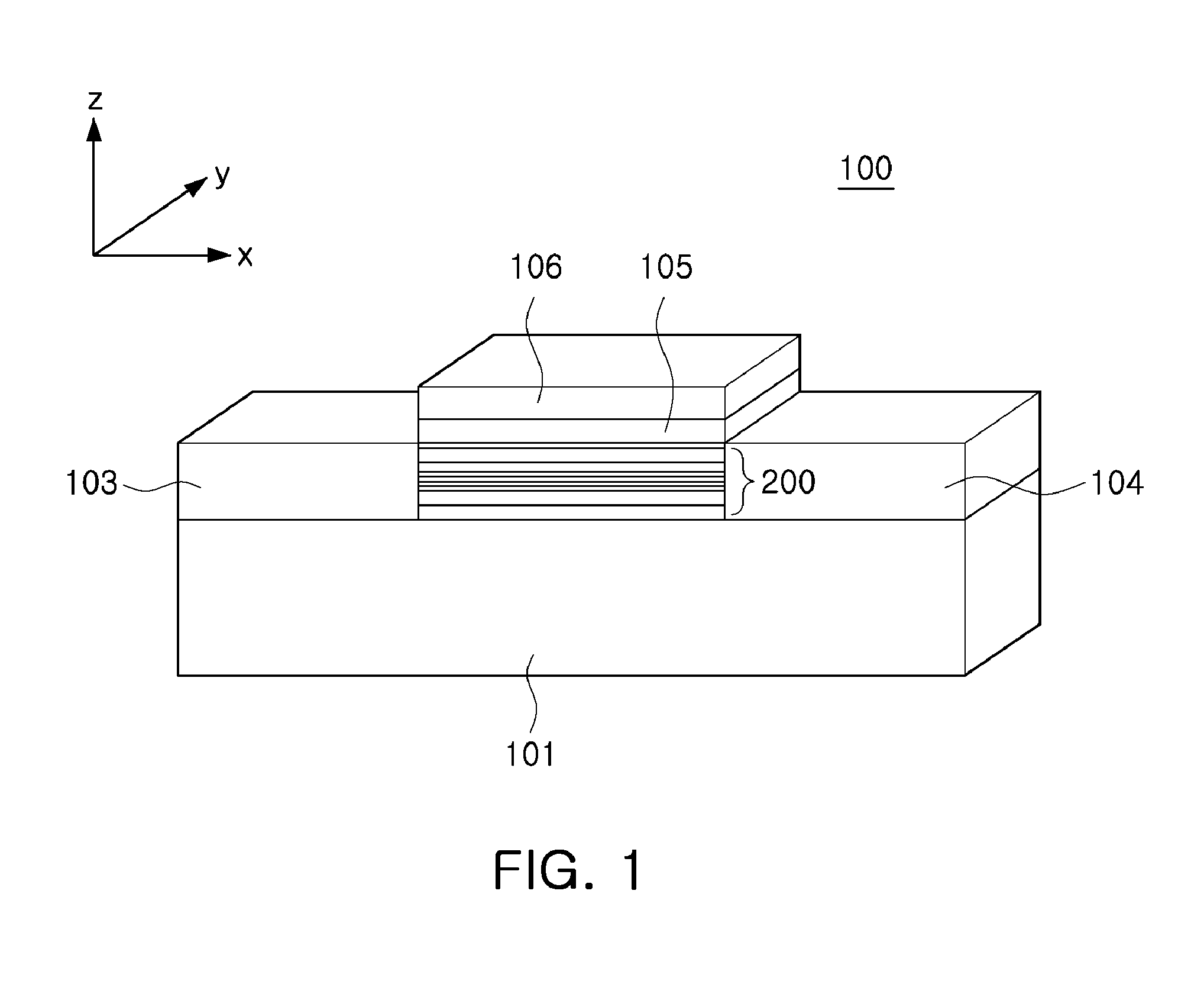
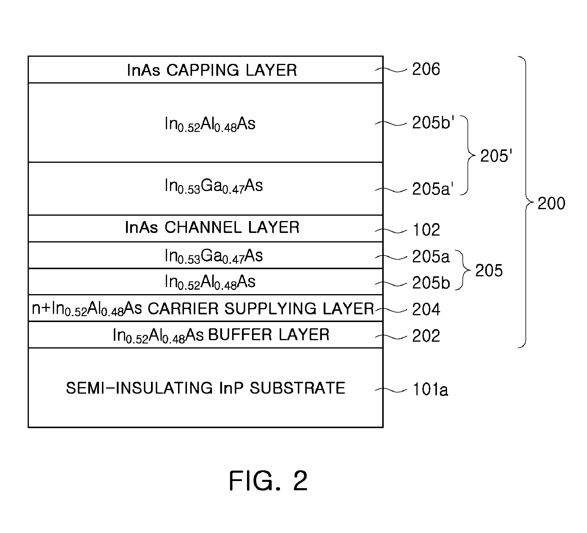
[0037]FIG. 1 is a diagram schematically showing a spin transistor according to an exemplary embodiment of the present invention. Referring to FIG. 1, the spin transistor includes a semiconduc...


PUM


Abstract

There is provided a complementary spin transistor logic circuit, including: a parallel spin transistor that includes a magnetized first source, a first drain magnetized in parallel with the magnetization direction of the first source, a first channel layer and a first gate electrode; and an anti-parallel spin transistor that includes a magnetized second source, a second drain magnetized in anti-parallel with the magnetization direction of the second source, a second channel layer and a second gate electrode, wherein the first gate electrode and the second gate electrode are connected to a common input terminal.

Description

CROSS-REFERENCE TO RELATED APPLICATIONS[0001]This application claims the priority of Korean Patent Application No. 10-2010-44330 filed on May 12, 2010, in the Korean Intellectual Property Office, the disclosure of which is incorporated herein by reference.BACKGROUND OF THE INVENTION[0002]1. Field of the Invention[0003]The present invention relates to a logic circuit, and more specifically, to a complementary spin transistor logic circuit.[0004]2. Description of the Related Art[0005]A semiconductor based logic device is the most important and value-added product in an integrated circuit performing complex functions. As a result, many research groups and companies are carrying out research into a semiconductor based logic device. The logic device, which is a fundamental device performing various operations, is a core device leading the semiconductor market, together with a memory device. The most frequently used logic circuit for electronic devices is a complementary MOS logic circuit...

Claims


Application Information

Patent Timeline
Patent Type & Authority Applications(United States)
IPC IPC(8): H03K19/091
CPCB82Y10/00H03K19/18G11C11/16H03K19/091H01L29/42312H01L29/78618H01L29/78624H01L29/78696
Inventor KOO, HYUN CHEOLHAN, SUK HEECHANG, JOON YEONKIM, HYUNG JUNCHOI, JUN WOO
Owner KOREA INST OF SCI & TECH
Learn More