
Device for exciting fluorescent samples using visible light or ultraviolet light

a fluorescent and ultraviolet light technology, applied in the direction of luminescent dosimeters, optical radiation measurement, fluorescence/phosphorescence, etc., can solve the problems of poor dynamic range of staining, low abundance of rare-message targets, and insufficient coomassie brilliant blue convenient dye binding, etc., to achieve better contrast and visualization, enhance visualization, and improve the s/n ratio.

Inactive Publication Date: 2011-11-17
CHEN HAN MIN +1
View PDF6 Cites 3 Cited by
  • Summary
  • Abstract
  • Description
  • Claims
  • Application Information

AI Technical Summary

Benefits of technology

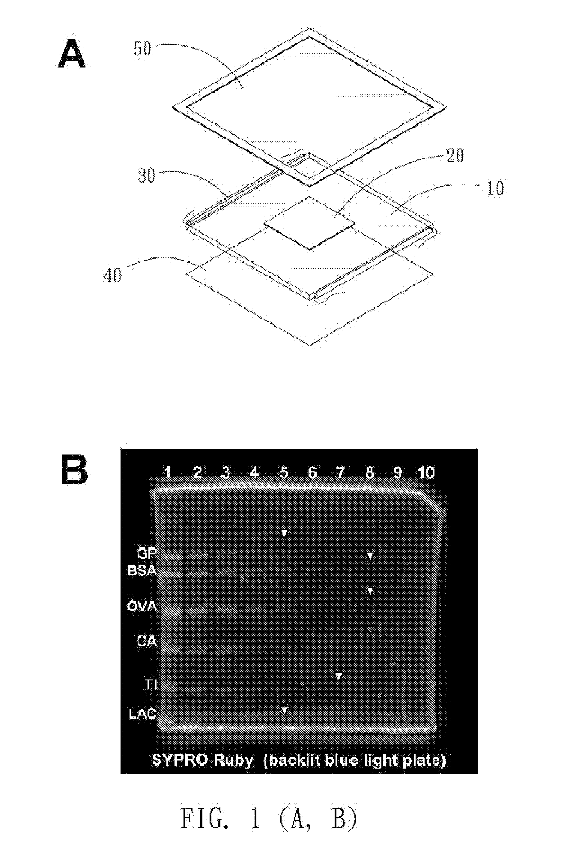
[0016]In the present invention, the inventors propose a device for exciting fluorescent samples using visible light or ultraviolet light, the device comprising, a transparent plate or strip as waveguide for guiding light; at least one lighting source placed alongside the transparent plate or strip; a transparent matrix; such that the fluorescent samples in the transparent matrix placed on waveguide of the device is excited by the light refracted from the waveguide to the transparent matrix according the Snell's Law; thus the exciting S / N ratio can be improved by the light refraction of the device. Wherein, the fluorescent samples is any one of the fluorescently stained or labeled DNA, Proteins or any other biological samples which can be excited by the guided light; the transparent plate or strip as waveguide is made of glass, plastic, quartz or any kind of materials that is transparent; the light source is linear cold cathode lamp (CCFL), light emitting diodes (LEDs) or any kind of light generating source that can emit visible light (wavelength big than or equal to 340 nm) or ultraviolet light (wavelength equal to or small than 340 nm); the transparent matrix placed on waveguide can be water, glycerin, natural transparent polymers such as agarose, synthetic polymers such as polyacrylamide or acrylic or any one of the materials that is transparent; the refractive index of the waveguide is larger than the refractive index of the transparent matrix; a black background is laid underneath of the waveguide for better contrast and visualization; a filter can be placed above the transparent matrix to shield irregularly refracted light for enhancing the visualization; the thickness of the waveguide is less than 1 cm; the thickness of the transparent matrix is less than 5 mm.

Problems solved by technology

Some proteins known as rare-message targets (e.g., interferons, lymphokines, and hormone receptors), however, are low in abundance and difficult to detect.
This poses a major problem in modern molecular biology since amplification techniques, such as polymerase chain reaction (PCR) for nucleotides, does not exist for protein amplification.
However, in many cases, the convenient dye-binding Coomassie Brilliant Blue is insufficient for revealing minor protein bands or spots.
High-sensitivity staining methods such as silver stain or imidazole-zinc reverse stain may reveal protein bands or spots as low as 1 ng, but deliver a poorer dynamic range of staining and have issues arising from mass spectral compatibility.
However, most gel image documentation instruments, such as laser gel scanners, are designed as closed systems and are not suitable for hands-on procedures.
First, direct and prolonged exposure in a UV radiation area is potentially hazardous to the operator, even when the appropriate safety equipment is utilized.
Second, not every fluorophore can be sufficiently excited by the UV light.
Fluorophores in some stains, such as Flamingo and Krypton, have low excitation maxima around 270 and 320 nm, making manual band or spot picking with UV transilluminators extremely difficult or impossible.
Third, most fluorophores are susceptible to UV light induced photobleaching.
Presumably, the broad bandwidth blue light makes it a less effective excitation light source than UV light.
Thus, applicability of blue light transilluminators is limited, as it is sometimes difficult to directly visualize weak fluorescent signals in protein gels with these apparatuses.

Method used


Image

  • Device for exciting fluorescent samples using visible light or ultraviolet light
  • Device for exciting fluorescent samples using visible light or ultraviolet light
  • Device for exciting fluorescent samples using visible light or ultraviolet light

Examples


Embodiment Construction

Materials and Methods—Preparation

[0021]A commercial standard protein mixture (GE Healthcare, Piscataway, N.J.) containing rabbit muscle glycogen phosphorylase b (GP), bovine serum albumin (BSA), chicken egg ovalbumin (OVA), bovine erythrocyte carbonic anhydrase (CA), soybean trypsin inhibitor (TI) and bovine lactalbumin (LAC) was two-fold serially diluted from 4,000 to 7.8 ng of total protein and separated by 15% SDS-PAGE. All electrophoretic procedures were performed according to standard protocol with minor modifications. The electrophoretic protein gels were treated by either SYPRO Ruby, SYPRO Tangerine, SYPRO Orange (Invitrogen, Grand Island, N.Y.), or DEEP PURPLE (GE Healthcare, Piscataway, N.J.) according to the manufacturers' instructions.

Gel Image Documentation and Analysis

[0022]A backlit blue light plate installed with two blue linear cold cathode fluorescent lamps (CCFLs) of 5 Watts (2000 lux, 30 cm), was purchased from Taiwan local electronic vendors. The blue light trans...


PUM


Abstract

This invention proposes a device for exciting fluorescent samples using visible light or ultraviolet light, the device comprising, a transparent plate or strip as waveguide for guiding light; at least one lighting source placed alongside the transparent plate or strip; a transparent matrix;such that the fluorescent samples in the transparent matrix placed on waveguide of the device is excited by the light refracted from the waveguide to the transparent matrix according the Snell's Law; thus the exciting S / N ratio can be improved by the light refraction of the device; wherein the light emitted from the light source with a primary incident angle larger than the critical angle of transparent plate or strip:air, but smaller than the critical angle of transparent plate or strip:matrix.

Description

[0001]This application is a continuation of prior application Ser. No. 12 / 291,768 filed on Nov. 14, 2008.BACKGROUND OF THE INVENTION[0002]1. Field of the Invention[0003]The invention relates to a device for exciting fluorescent samples using visible or ultraviolet light. More particularly, the invention relates to a device for exciting fluorescently stained or labeled molecules in transparent matrix using waveguide under Snell's law for improving the signal to noise (S / N) ratio.[0004]2. Description of the Related Art[0005]Proteomics may be one of the most fascinating-omics in current life science research. With the remarkable advances in separation and identification techniques, in a high throughput way, proteomics allows for the identification of differentially expressed or modified proteins between experimental and control groups, or pathological and healthy samples. Since proteins are the terminally expressed molecules of signaling cascades, they more directly reflect the physiol...

Claims


Application Information

Patent Timeline
IPC IPC(8): G01N21/64
CPCG01N21/6456
Inventor CHEN, HAN-MINCHEN, LI-MING
Owner CHEN HAN MIN
Learn More