Power supply system and electronic device
a power supply system and electronic device technology, applied in the field of power supply systems, can solve the problems of large relative electricity loss and needless electricity loss, and achieve the effects of preventing overload on a specific power supply device due to the variation of characteristics and deterioration degree among the respective power supply devices, preventing current flow among the different power supply devices, and preventing overload on the specific power supply devi
Active Publication Date: 2011-11-03
MURATA MFG CO LTD
View PDF3 Cites 8 Cited by
- Summary
- Abstract
- Description
- Claims
- Application Information
AI Technical Summary
Benefits of technology
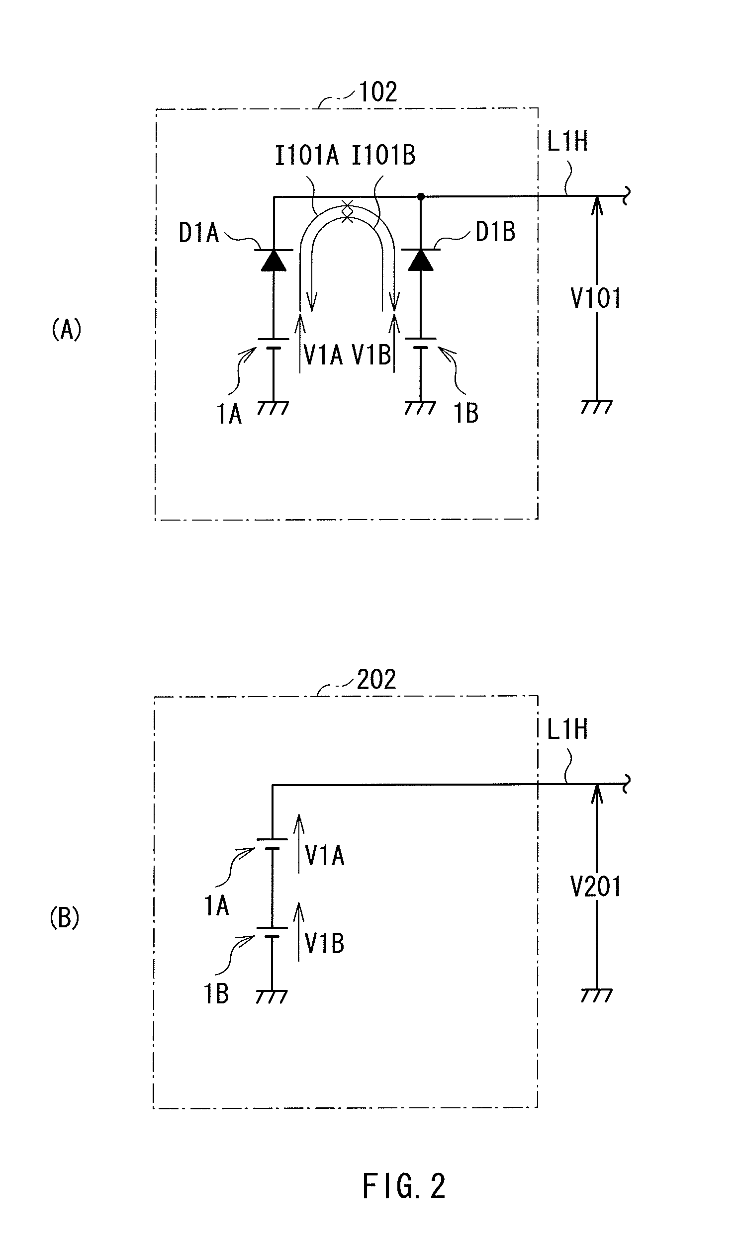
[0012]Therefore, to solve the foregoing problems, a method using a rectifier (diode) may be a candidate method. Specifically, in the method, by connecting the diode in series with each battery that is connected in parallel with each other, current flow from other battery is prevented while high stability is obtained.
[0014]In performing electricity supply by using a plurality of power supply devices as above, it is desirable to inhibit electricity loss and deterioration of each power supply device while high stability is realized.
[0015]In view of the foregoing problems, it is an object of the present invention to provide a power supply system capable of suppressing electricity loss and deterioration of each power supply device while realizing high stability in the case where electricity supply is performed by using a plurality of power supply devices, and an electronic device including such a power supply system.
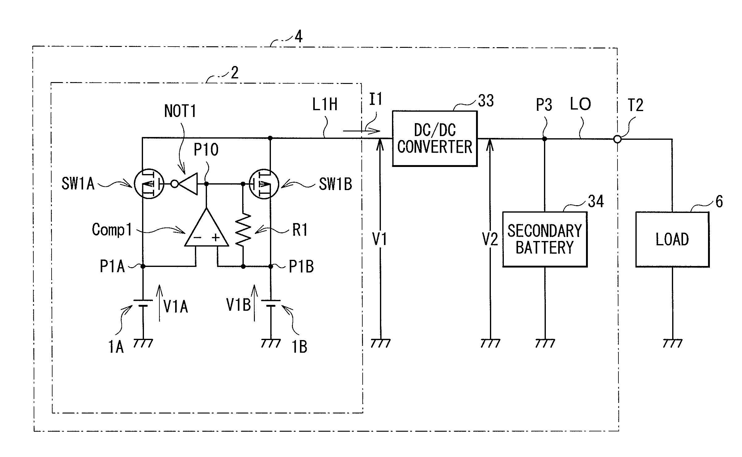
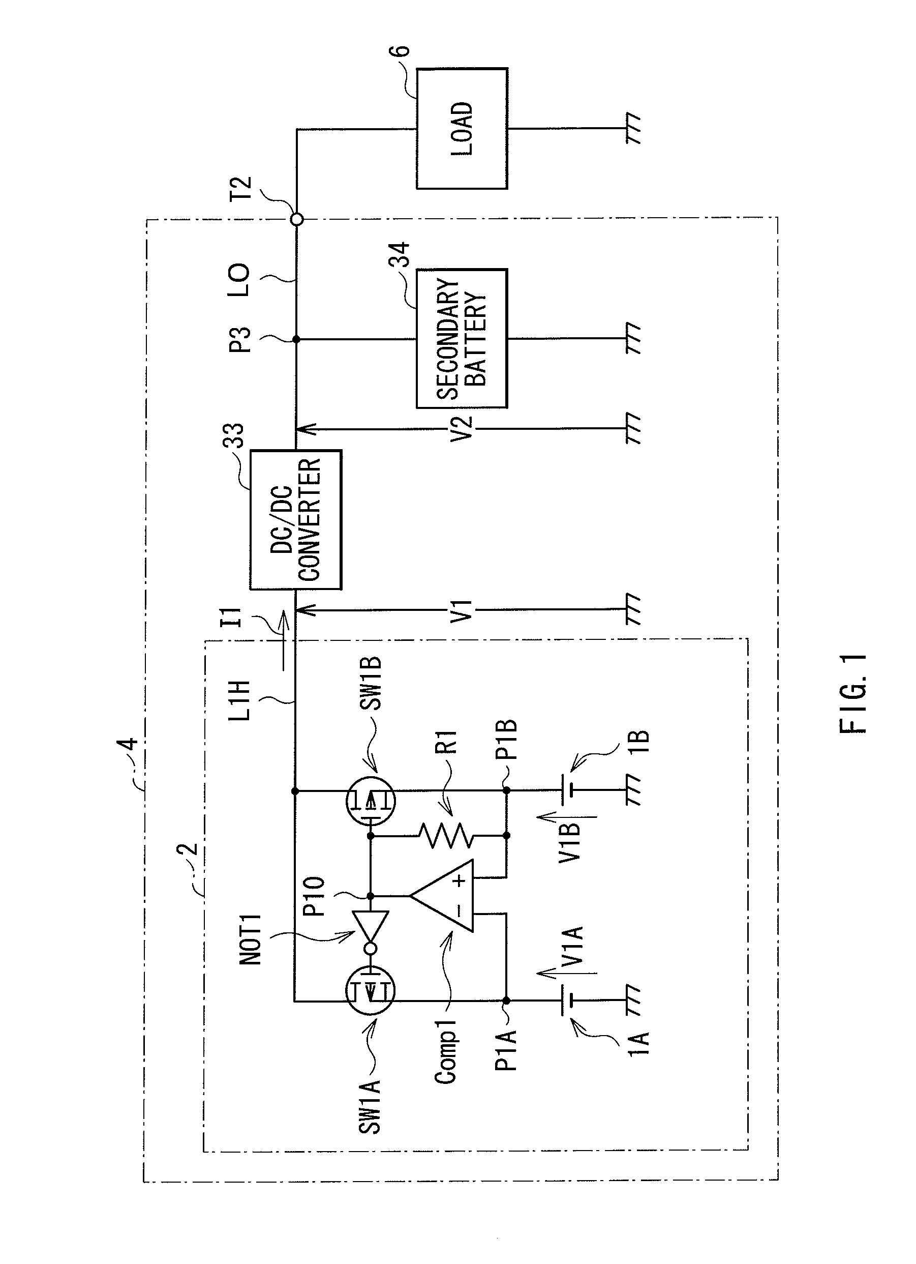
[0019]In the power supply system and the electronic device according to the embodiment of the present invention, ON / OFF state of the respective switching elements is controlled so that the switching element corresponding to the power supply device having the highest inter-terminal voltage among the plurality of power supply devices selectively becomes in ON state, and the switching element corresponding to the other power supply devices becomes in OFF state. Thereby, overload on a specific power supply device due to variation of characteristics and variation of deterioration degree among the respective power supply devices is prevented. Further, since the switching element corresponding to the power supply device having the highest inter-terminal voltage selectively becomes in ON state, current flow between the different power supply devices is prevented without generating needless electricity loss different from an existing case using a diode. Further, since electricity of the power supply device having the highest inter-terminal voltage is selectively outputted, variation among the respective power supply devices becomes allowable to some extent, compared to a case that output is made by connecting a plurality of power supply devices in series with each other.
[0020]According to the power supply system and the electronic device according to the embodiment of the present invention, ON / OFF state of the respective switching elements is controlled so that the switching element corresponding to the power supply device having the highest inter-terminal voltage among the plurality of power supply devices selectively becomes in ON state, and the switching element corresponding to the other power supply devices becomes in OFF state. Thus, overload on a specific power supply device is prevented, and current flow among the different power supply devices is able to be prevented without generating needless electricity loss. Further, since electricity of the power supply device having the highest inter-terminal voltage is selectively outputted, variation among the respective power supply devices becomes allowable to some extent. Thus, in the case where electricity supply is performed by using a plurality of power supply devices, electricity loss and deterioration of each power supply device are able to be inhibited while high stability is realized.
Problems solved by technology
However, in the power generating device having low electromotive force such as a fuel cell and a solar cell, even if the Schottky barrier diode is used, relative electricity loss becomes large, resulting in a problem.
Method used
View moreImage
Smart ImageViewing Examples

Examples
first embodiment (
1. First embodiment (basic structure example for connection switching in an electricity supply section)
second embodiment (
2. Second embodiment (multistage structure example for connection switching in an electricity supply section)
third embodiment (
3. Third embodiment (structure example for charge and discharge dual-use in the case of using a secondary battery)
Login to View More PUM
 Abstract
A power supply system capable of inhibiting electricity loss and deterioration of each power supply device while realizing high stability in the case where electricity supply is performed by using a plurality of power supply devices is provided. A switching element corresponding to a power supply device having a higher inter-terminal voltage out of two power supply devices selectively becomes in ON state, and a switching element corresponding to a power supply device having a lower inter-terminal voltage selectively becomes in OFF state. Thereby, overload on a specific power supply device is prevented, and current flow between the different power supply devices is able to be prevented without generating needless electricity loss. Further, since electricity of the power supply device having a higher inter-terminal voltage is selectively outputted, variation between the respective power supply devices becomes allowable to some extent.
Description
TECHNICAL FIELD[0001]The present invention relates to a power supply system having a plurality of power supply devices and an electronic device including such a power supply system.BACKGROUND ART[0002]A power supply device such as a primary battery including a dry battery, a secondary battery such as a lithium ion battery, and a power generating device such as a fuel cell and a solar cell is used as an assembled battery in which a plurality of cells are connected in series or in parallel with each other to meet electricity demand of electronic devices.[0003]However, in the case where characteristics and deterioration degree of each power supply device varies, a specific power supply device suffers overload. Accordingly, characteristics as an assembled battery are lowered. In some cases, a dangerous failure is caused thereby.[0004]For example, in the case where an assembled battery is configured by connecting a plurality of cells in series, variation of the respective cells becomes a...
Claims
Login to View More Application Information
Patent Timeline
 Patent Type & Authority Applications(United States)
IPC IPC(8): H02J1/10
CPCH01M8/04559H01M8/0488H01M8/04955H01M10/0525H01M10/441H01M10/465Y02E60/50H01M16/003H01M2250/30H02J1/10H02J7/34Y02B90/18H01M16/00Y02B90/10Y02E60/10H01J7/34
Inventor SHIMURA, JUSUKEINOUE, YOSHIAKI
Owner MURATA MFG CO LTD
Features
- R&D
- Intellectual Property
- Life Sciences
- Materials
- Tech Scout
- Unparalleled Data Quality
- Higher Quality Content
- 60% Fewer Hallucinations
Learn More Browse by: Latest US Patents, China's latest patents, Technical Efficacy Thesaurus, Application Domain, Technology Topic, Popular Technical Reports.
© 2025 PatSnap. All rights reserved.Legal|Privacy policy|Modern Slavery Act Transparency Statement|Sitemap|About US| Contact US: help@patsnap.com