RF coil for MRI apparatus, method of using RF coil for MRI apparatus, and MRI apparatus

a technology of rf coil and mri coil, which is applied in the direction of instruments, magnetic measurements, measurement devices, etc., can solve the problems of deteriorating transmission efficiency of rf pulse and receiving sensitivity of magnetic resonance signal in 8-shaped coil b>2/b>, and achieve the effect of improving the transmission efficiency of rf pulse and receiving sensitivity of magnetic resonance signal, and reducing the number of decoupling circuits

Inactive Publication Date: 2009-08-18
GE MEDICAL SYST GLOBAL TECH CO LLC
View PDF9 Cites 1 Cited by
  • Summary
  • Abstract
  • Description
  • Claims
  • Application Information

AI Technical Summary

Benefits of technology

[0013]In one aspect of the invention, an RF coil for an MRI apparatus according to the present invention includes: a figure-8 coil having an 8-shaped configuration in which a conductive path crosses; and an impedance adjustment coil that performs connection between crossing points of the conductive path, wherein the crossing points of the conductive path are connected in parallel through the impedance adjustment coil and a floating capacitance between the crossing points of the conductive path, and in a Larmor frequency that is in proportion to the intensity of a magnetostatic field, an impedance between the crossing points of the conductive path is increased and a current that flows between the crossing points of the conductive path is reduced.
[0017]Also, according to the invention, there is provided a method of using an RF coil for an MRI apparatus that includes a figure-8 coil having an 8-shaped configuration in which a conductive path crosses, and an impedance adjustment coil that performs connection between crossing points of the conductive path, wherein the crossing points of the conductive path are connected in parallel through the impedance adjustment coil and a floating capacitance between the crossing points of the conductive path, and the method comprises applying a magnetostatic field of an intensity that an impedance between the crossing points of the conductive path is increased and a current that flows between the crossing points of the conductive path is reduced.
[0021]Also, an MRI apparatus according to the invention includes an RF coil having a figure-8 coil of an 8-shaped configuration in which a conductive path crosses, and an impedance adjustment coil that performs connection between crossing points of the conductive path, wherein the crossing points of the conductive path are connected in parallel through the impedance adjustment coil and a floating capacitance between the crossing points of the conductive path, and in a Larmor frequency that is in proportion to the intensity of a magnetostatic field, an impedance between the crossing points of the conductive path is increased, and a current that flows between the crossing points of the conductive path is reduced, and wherein the RF coil is allowed to transmit the RF pulse, receive the magnetic resonance signal, or transmit the RF pulse and receive the magnetic resonance signal.
[0025]According to the invention, it is possible to reduce the number of decoupling circuits in an MRI apparatus, and improve the transmission efficiency of an RF pulse and the receiving sensitivity of a magnetic resonance signal in an RF coil having an 8-shaped configuration, with a reduction of a current that flows through the floating capacitance of the crossing points of a conductive path in the RF coil having the 8-shaped configuration.

Problems solved by technology

However, in this method, because the resistance of the conductive path in the crossing points is large, the transmission efficiency of the RF pulse and the receiving sensitivity of the magnetic resonance signal in the 8-shaped coil 2 deteriorate.

Method used


Image

  • RF coil for MRI apparatus, method of using RF coil for MRI apparatus, and MRI apparatus
  • RF coil for MRI apparatus, method of using RF coil for MRI apparatus, and MRI apparatus
  • RF coil for MRI apparatus, method of using RF coil for MRI apparatus, and MRI apparatus

Examples


Embodiment Construction

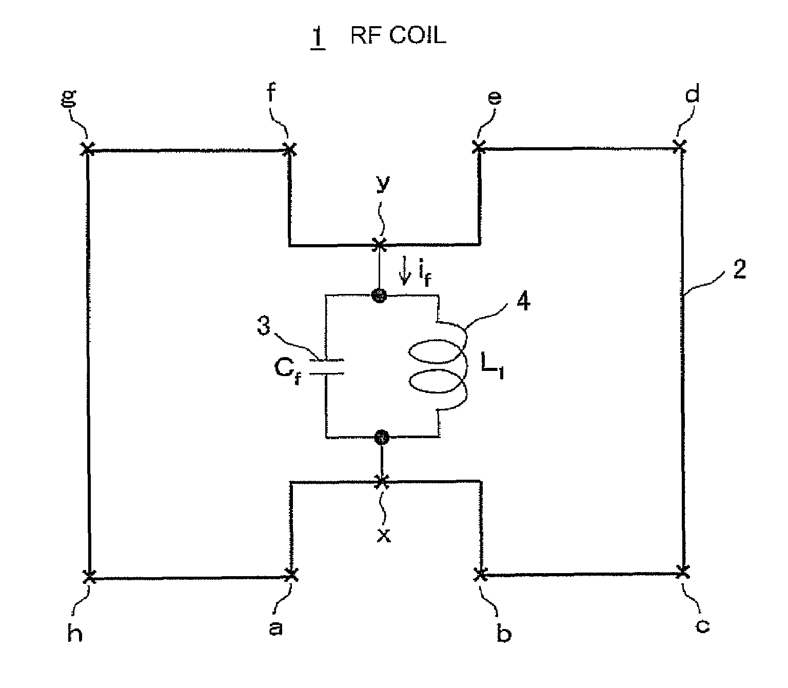
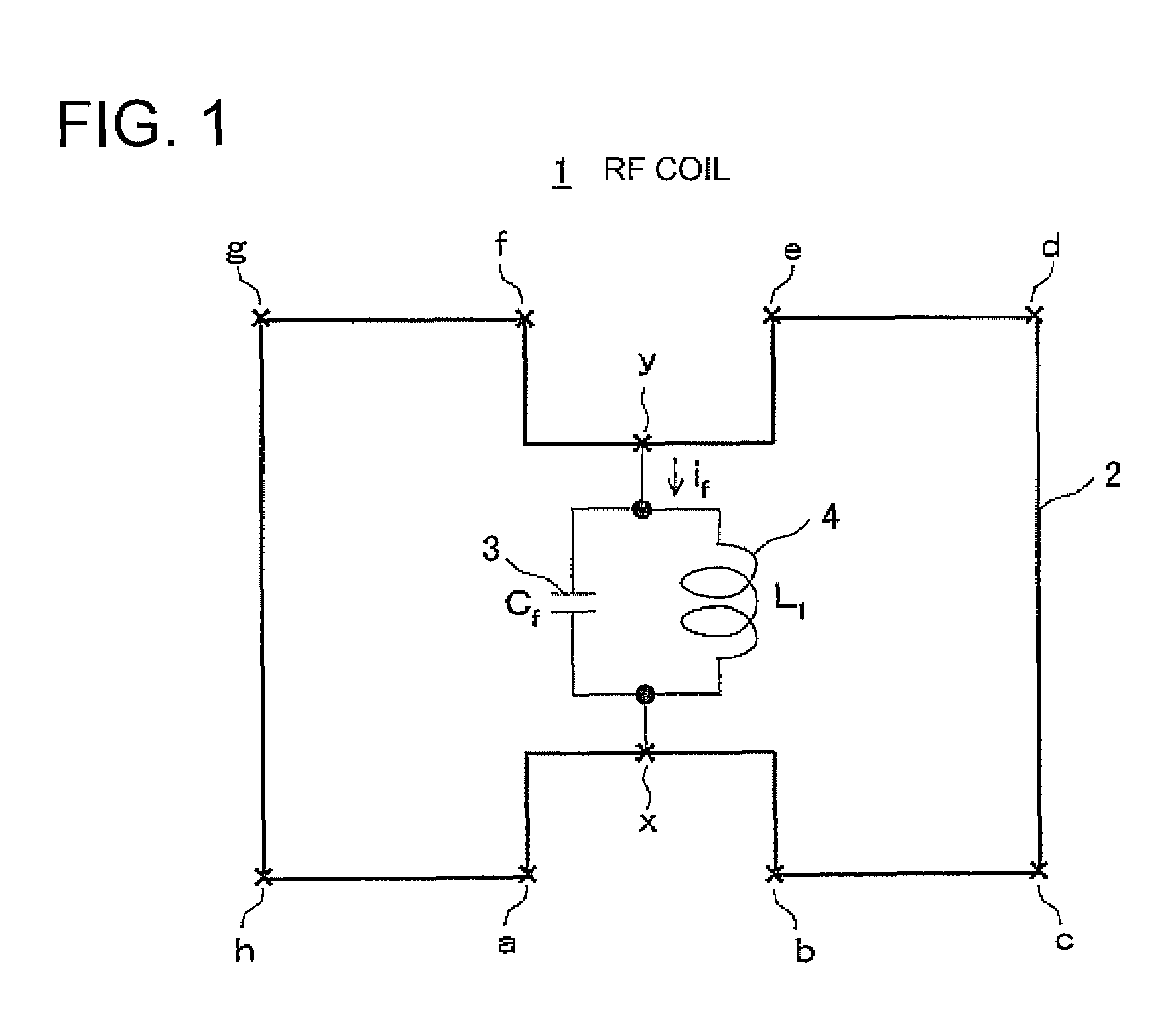
[0034]FIG. 1 is a diagram showing an RF coil according to a first embodiment of the invention. An RF coil 1 is made up of an 8-shaped coil 2, and an impedance adjustment coil 4 that performs connection between an x point and a y point at which a conductive path of the 8-shaped coil 2 crosses. Because a floating capacitance 3 that is determined according to a geometric configuration of an overlapped portion is developed between the x point and the y point, the x point and the y point are connected in parallel by the floating capacitance 3 and the impedance adjustment coil 4. The 8-shaped coil 2 shown in FIG. 1 is a development of the crossing points of the conductive path on a plane, and the conductive path of the 8-shaped coil 2 actually has a given width, but is indicated by a line for simplification.

[0035]When it is assumed that the inductance of the impedance adjustment coil 4 is L1, an impedance Z1 between the x point and the y point is represented by the following expression in...


PUM


Abstract

A RF coil according to the invention is made up of an 8-shaped coil having a crossed conductive path, and an impedance adjustment coil that performs connection between crossing points of the conductive path. The crossing points of the conductive path are connected in parallel by the impedance adjustment coil and a floating capacitance between the crossing points of the conductive path. An impedance between the crossing points of the conductive path is increased, and a current that flows between the crossing points of the conductive path reduces in a Larmor frequency that is in proportion to the intensity of the magnetostatic field of an MRI apparatus. The RF coil according to the invention is made up of an 8-shaped coil having a crossed conductive path, an impedance adjustment coil that performs connection between the crossing points of the conductive path in parallel, and an impedance adjustment coil.

Description

CROSS REFERENCE TO RELATED APPLICATIONS[0001]This application claims the benefit of Japanese Patent Application No. 2006-308741 filed Nov. 15, 2006.BACKGROUND OF THE INVENTION[0002]The present invention relates to an RF coil for an MRI apparatus, a method of using the RF coil for an MRI apparatus, and the MRI apparatus. More particularly, the present invention relates to an RF coil for an MRI apparatus having a Figure-8 configuration for receiving a magnetic resonance signal from an object to be detected, a method of using the RF coil for an MRI apparatus, and an MRI apparatus using the method. The coil having a figure-8 configuration is referred to herein as an 8-shaped coil.[0003]The MRI apparatus generates a magnetic resonance signal by the aid of a magnetic resonance phenomenon, and takes a tomographic image of the object to be detected. In the MRI apparatus, an improvement in the efficiency of the RF coil that transmits the RF pulse and receives the magnetic resonance signal is...

Claims


Application Information

Patent Timeline
Patent Type & Authority Patents(United States)
IPC IPC(8): G01V3/00
CPCG01R33/341G01R33/3678G01R33/3628
Inventor NABETANI, AKIRA
Owner GE MEDICAL SYST GLOBAL TECH CO LLC
Why Eureka
Try Eureka