Induction coil, method and device for inductive heating of metallic components

a technology of induction coils and metallic components, which is applied in the direction of induction heating, electric/magnetic/electromagnetic heating, electrical apparatus, etc., can solve the problems of uneven heating of the joining faces of known induction coils, difficult to achieve uniform heating of the components to be machined and joined, and increase the current flow between the two faces to be joined, so as to achieve uniform heating and easy extraction

Inactive Publication Date: 2009-05-21
MTU AERO ENGINES GMBH
View PDF70 Cites 6 Cited by
  • Summary
  • Abstract
  • Description
  • Claims
  • Application Information

AI Technical Summary

Benefits of technology

[0018]A device according to an embodiment of the present invention for inductive heating of metallic components, in particular components of a gas turbine, where the components each have one or more lateral faces surrounding the particular component cross section, has at least one generator and at least one induction coil, the induction coil being designed in a meandering pattern and shaped around the component(s), in such a way that the induction coil extends over at least a partial area of the lateral face(s) of the component(s) to be heated in the area of one or more faces to be heated. In contrast with conventional devices for inductive heating, machining or heating of the components takes place via an induction coil having a meandering pattern and a three-dimensional design. In this way, the current flow may be guided in such a way that it acts over the entire area of the faces to be machined or the joining faces and thus uniform heating of the entire machining face or joining zone is achieved, independently of the cross section of the components. Furthermore, the current flow between two faces to be joined is increased. In addition, the device according to the present invention allows input of heat into faces of varying width; furthermore, the component to be machined may be easily extracted out of the device because the induction coil used usually does not completely surround the component.
[0019]In another advantageous embodiment of the device according to the present invention, the three-dimensional design of the induction coil is adapted to the geometry of the component(s). Due to this adaptation, uniform heating of all faces to be machined in the working range of the induction coil is ensured.
[0020]In another advantageous embodiment of the device according to the present invention, the three-dimensional design of the induction coil is designed in such a way that the current on the face(s) flows perpendicularly to the areas of the induction coil parallel to one another on a top side and a bottom side of the components. This also ensures uniform heating of the entire face to be machined or the faces to be joined together.
[0021]In another advantageous embodiment, the device has at least one cooling device for the induction coil. The cooling device ensures that there is no damage to the induction coil, e.g., due to the temperature input into the induction coil being too high.
[0022]In another advantageous embodiment of the device according to the present invention, inductive heating is an inductive low-frequency or high-frequency pressure welding method for joining metallic components, in particular components of a gas turbine. The frequencies used here may be selected from a range between 0.05 and 2.5 MHz. Due to the uniform heat input regardless of the cross section of the components to be joined, the device according to the present invention is suitable in particular for joining appropriate metallic components. Furthermore, the device may have means which allow inductive low- or high-frequency pressure welding to be performed in a vacuum or in a protective gas atmosphere. This contributes toward the quality of the resulting welds.
[0023]In other advantageous embodiments of the device according to the present invention, an insulator is situated at least partially between the induction coil and the component(s) in the area of the sections of the components to be heated or to be joined, the insulator having at least one face which faces the component(s) and is made of a material that does not essentially or at all hinder the magnetic interaction between the induction coil and the components to be heated due to its specific properties. Furthermore, the face of the insulator may be designed to be a distance away from the induction coil and / or the component(s). The insulator may be made of glass, for example, in particular refractory quartz glass, a refractory ceramic or a refractory plastic. In the case of the device, the induction coil is advantageously and reliably insulated when metal vapor is formed due to the vaporization of the surfaces of the components to be heated, thus no plasma is formed and no short circuit occurs between the components and the induction coil. Moreover, the device may also keep on operating continuously and without interference as required in automatic mass production of components, for example, even when a metal vapor is formed. Furthermore, according to an embodiment of the present invention, the magnetic interaction between the insulator and the components is not hindered due to a suitable choice of material of the insulator. Due to a possible spacing of the face of the insulator away from the induction coil, this ensures that there are no stresses between the induction coil and the insulator and / or the component and the insulator due to possible temperature-dependent differences in thermal expansion between these elements.

Problems solved by technology

Essentially, the problem that arises with methods for inductive heating of metallic components is that a uniform heating of the components to be machined and joined is very difficult to achieve independently of their cross section.
With large and / or almost square joining faces in particular, the current flow and thus the heating of the joining faces by known induction coils are uneven.

Method used


Image

  • Induction coil, method and device for inductive heating of metallic components
  • Induction coil, method and device for inductive heating of metallic components
  • Induction coil, method and device for inductive heating of metallic components

Examples


Embodiment Construction

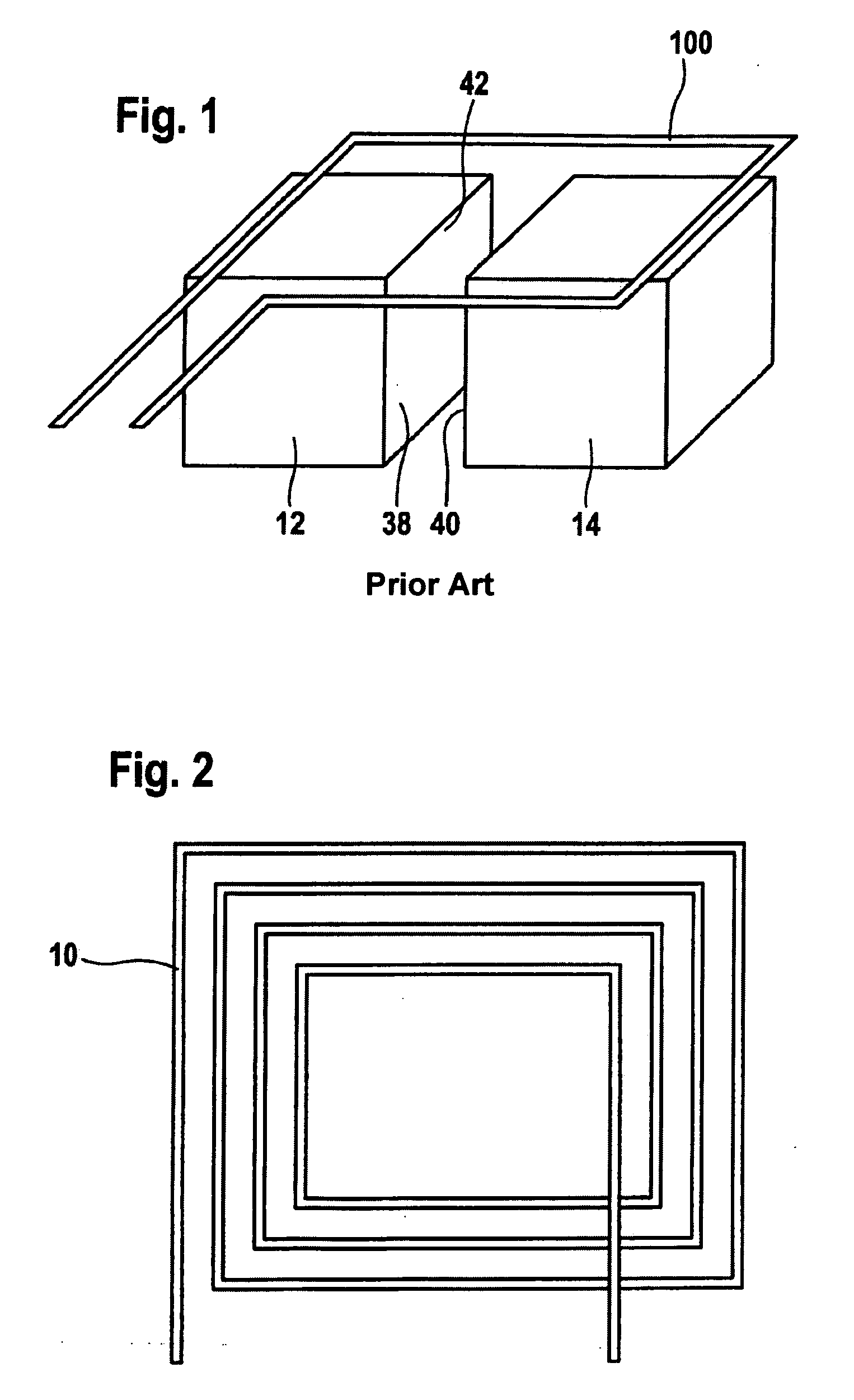
[0032]FIG. 1 shows a schematic diagram of an induction coil 100 according to the related art. This shows the flat design of induction coil 100 having two components 12, 14 to which opposing joint faces 38, 40 are to be joined by inductive low- or high-frequency pressure welding. However, due to the flat design of induction coil 100, only a partial area of joining faces 38, 40, namely in particular an edge area 42, which is closest to induction coil 100 is heated. It is apparent that there is no direct heating via induction coil 100 in particular at the center of joining faces 38, 40.

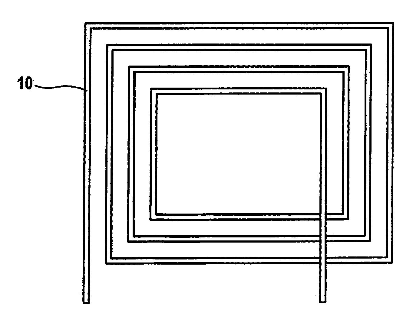
[0033]FIG. 2 shows a schematic diagram of an induction coil 10 according to one exemplary embodiment of the present invention. Induction coil 10 is shown in an unfolded state; the meandering design of an induction coil 10 is clearly apparent. Other meandering forms, e.g., having rounded corner areas, are also conceivable. Induction coil 10 is usually made of copper or a copper alloy. Other metals or meta...


PUM


Abstract

An induction coil for inductive heating of at least one metallic component having at least one lateral face and at least one face to be heated is provided. The induction coil includes a meandering pattern section shaped around the at least one component in such a way that the section extends over at least a partial area of the at least one lateral face of the at least one component to be heated in the area of the at least one face to be heated. A device and method for inductive heating of at least one metallic component are also provided.

Description

[0001]This application claims priority to German Patent Application DE 10 2007 054 782.1, filed Nov. 16, 2007, which is incorporated by reference herein.[0002]The present invention relates to an induction coil for use in a method for inductive heating of metallic components, in particular components of a gas turbine, each component having one or more lateral faces surrounding the particular component cross section. The present invention also relates to a method and a device for inductive heating of metallic components, in particular components of a gas turbine, and a component manufactured by this method.BACKGROUND[0003]DE 198 58 702 A1 describes a pressure welding method for joining blade components of a gas turbine in which a vane section and at least one other blade component are provided. Corresponding joining faces of these elements are positioned essentially flush and at a distance from one another and are then joined together by exciting an inductor with a high-frequency curr...

Claims


Application Information

Patent Timeline
Patent Type & Authority Applications(United States)
IPC IPC(8): H05B6/36
CPCH05B6/101H05B6/40H05B6/36
Inventor BAMBERG, JOACHIMGINDORF, ALEXANDERHANRIEDER, HERBERTZENZINGER, GUENTER
Owner MTU AERO ENGINES GMBH
Why Eureka
Try Eureka