
Mass spectrometer and mass spectrometry method

a mass spectrometer and mass spectrometry technology, applied in mass spectrometers, stability-of-path spectrometers, separation processes, etc., can solve the problems of difficult to distinguish between molecule ions, insufficient information, and complicated sample contents, so as to reduce crosstalk, high ion transmission efficiency, and low cost

Inactive Publication Date: 2011-10-13
HITACHI HIGH-TECH CORP
View PDF23 Cites 22 Cited by
  • Summary
  • Abstract
  • Description
  • Claims
  • Application Information

AI Technical Summary

Benefits of technology

[0033]According to the present invention, it is made possible to implement a quadrupole mass filter that has a high ion transmission efficiency even under a high pressure and can be fabricated at low cost.
[0034]In addition, according to one aspect of the present invention, it is made possible to provide a mass spectrometer or mass spectrometry method that reduces crosstalk in a wide mass range.
[0035]According to another aspect of the present invention, ion acceleration in the axial direction due to resonant excitation and the voltage at a frequency corresponding to a high mass are selectively increased, so that it is made possible to shorten a time period for which ions in a wide mass-to-charge ratio range stay in the collision cell for reducing crosstalk.

Problems solved by technology

However, constituents in the sample are sometimes complicated, or the obtained mass spectrum sometimes has information insufficient for identifying a component.
More particularly, because the mass spectrometer identifies a molecule ion by a mass-to-charge ratio, it becomes difficult to distinguish between molecule ions if mass-to-charge ratios are the same or if the resolution of the mass spectrometer is poor even though ions have different structures.
In addition, in a mass spectrum in which a mass-to-charge ratio is 400 or less, it is impossible to distinguish a target component from impurities because there are many impurities in a solvent or impurities derived from an environment.

Method used


Image

  • Mass spectrometer and mass spectrometry method
  • Mass spectrometer and mass spectrometry method
  • Mass spectrometer and mass spectrometry method

Examples


embodiment 1

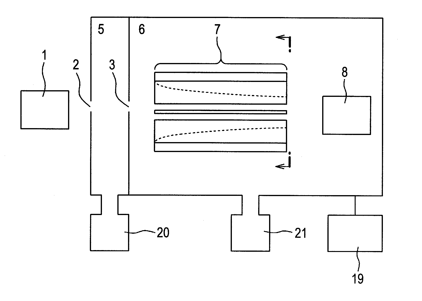
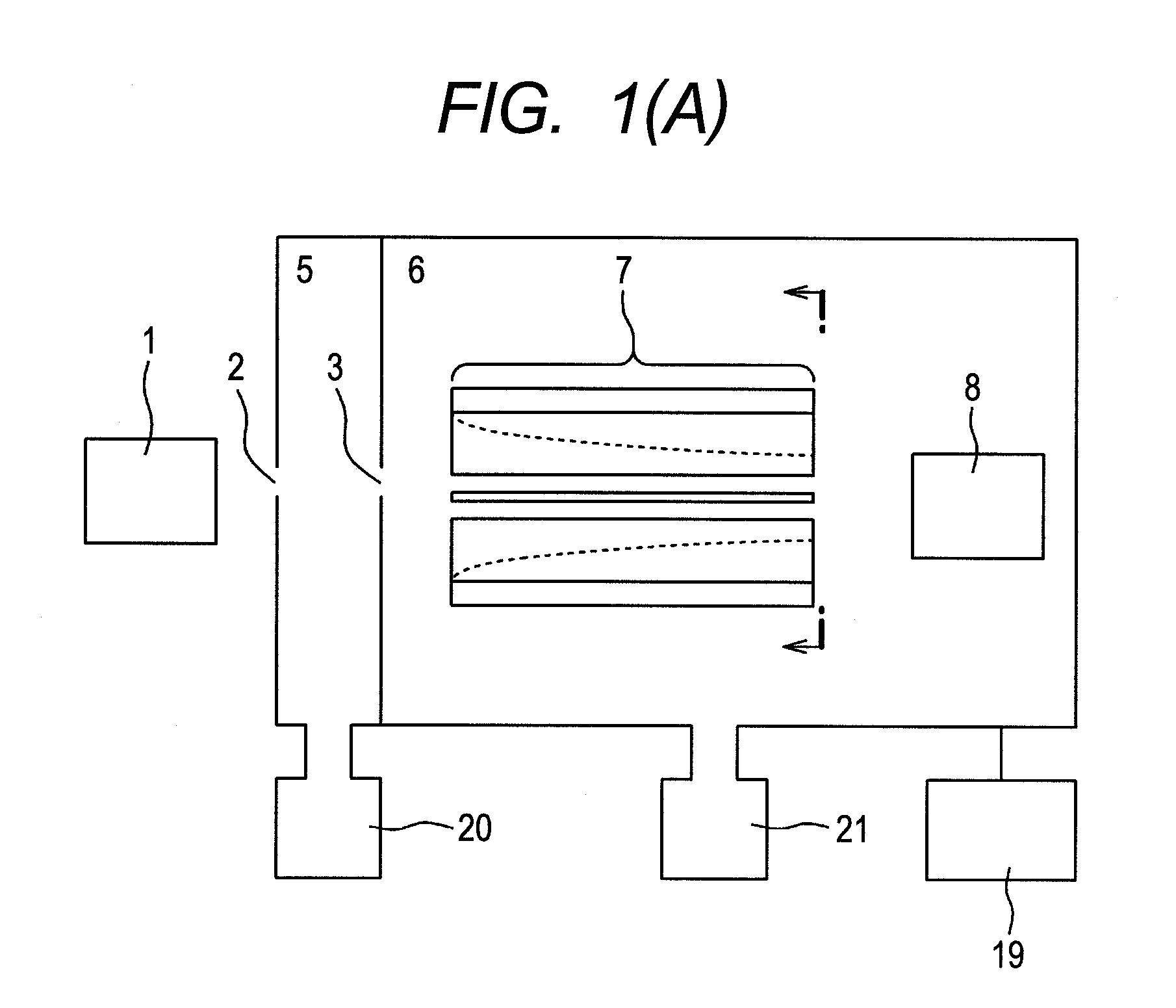
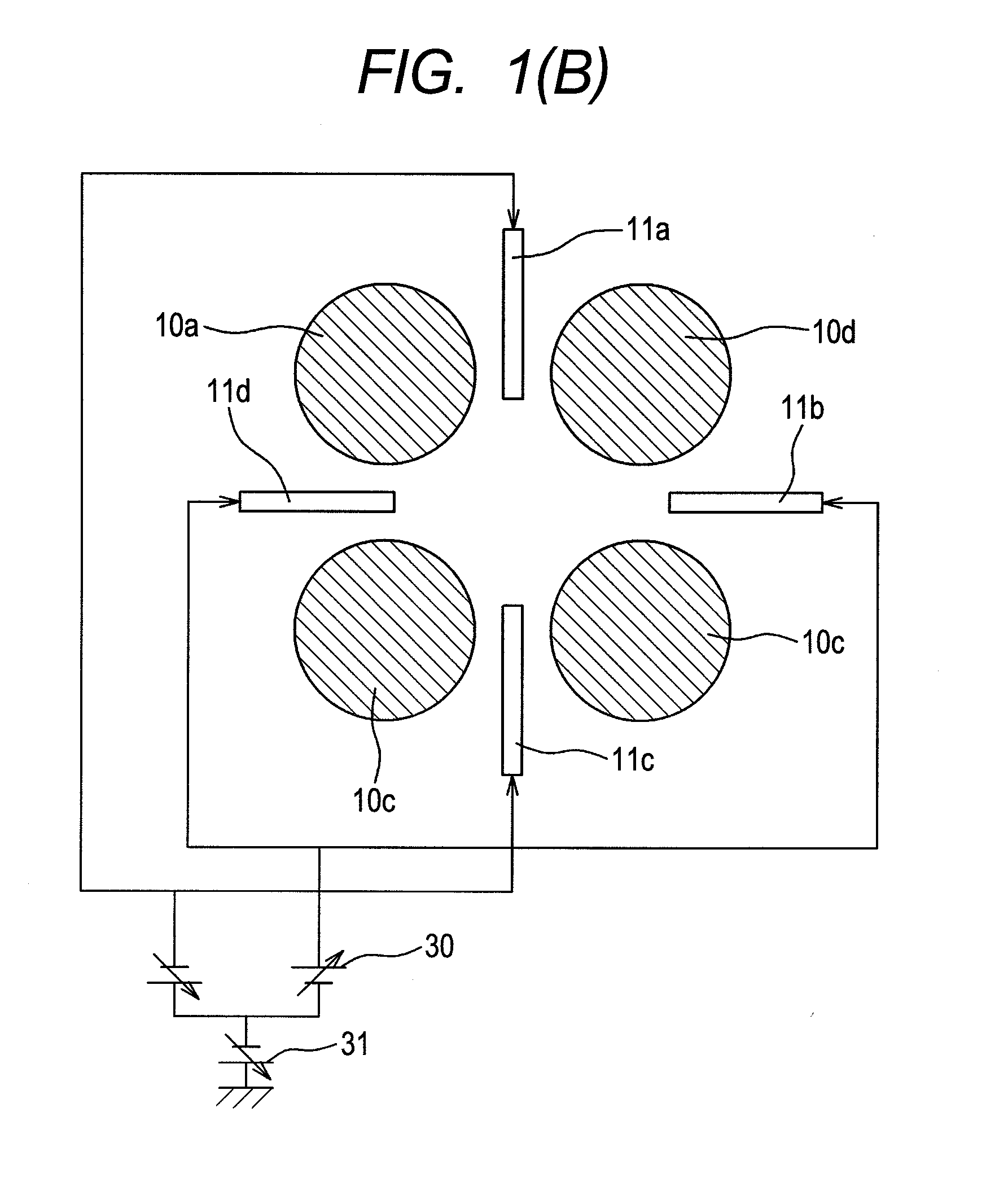
[0063]FIG. 1 shows block diagrams depicting a mass spectrometer according to this scheme. FIG. 1(A) is a diagram of the overall device, FIG. 1(B) is an axial cross sectional view depicting a quadrupole mass filtering unit 7, and FIGS. 1(C) and 1(D) are radial cross sectional views.

[0064]Ions produced in an ion source 1 such as an electrospray ion source, atmospheric pressure chemical ion source, atmospheric pressure optical ion source, atmospheric pressure matrix-assisted laser desorption / ionization source, and matrix matrix-assisted laser desorption / ionization source are passed through an aperture 2, and introduced into a differential pumping unit 5. The differential pumping unit is evacuated by a pump 20. The ions are passed from the differential pumping unit 5 through an aperture 3, and introduced into an analyzing unit 6. The analyzing unit is evacuated by a pump 21, and maintained at a pressure of 10−1 Torr or below (1.3 Pa or below). The ions are introduced into a quadrupole m...

embodiment 2

[0075]In an embodiment 2, a configuration will be described in which both ends of the quadrupole electrostatic electrodes 11 exist inner than both ends of the quadrupole rod electrodes 10.

[0076]FIG. 5(A) is an axial cross sectional view depicting the mass spectrometer, to which this scheme is implemented. Moreover, FIG. 5(B) is a radial cross sectional view seen from the direction of an arrow shown in FIG. 5(A). Furthermore, FIG. 5(B) shows a manner of voltage application to the quadrupole electrostatic electrodes 11. The device configuration to a quadrupole mass filtering unit 7 and the device configuration after the quadrupole mass filtering unit 7 are the same as those in the embodiment 1 for omission.

[0077]In the quadrupole mass filtering unit 7, quadrupole electrostatic electrodes are disposed in the inner side of quadrupole rods, as formed of an inlet side focusing section 40, a mass separating section 41, and an exit side focusing section 42. The quadrupole RF voltage amplitu...

embodiment 3

[0081]In an embodiment 3, the configuration will be described in which this scheme is incorporated in a linear ion trap. The structure of a linear ion trapping unit is shown in FIG. 6. The linear ion trapping unit is formed of an inlet end electrode 27, quadrupole rod electrodes 10, an outlet end electrode 28, quadrupole electrostatic electrodes 11, a trap wire electrode 24, and a lead wire electrode 25. A buffer gas is introduced into the linear ion trapping unit, which is maintained at a pressure of about 10−4 Torr to 10−2 Torr (1.3×10⁻² Pa to 1.3 Pa).

[0082]FIG. 7 shows the measuring sequence of the linear ion trapping unit. The measurement is performed in three sequences, trapping, mass scanning, and removal. In a trap time period, a voltage of the same polarity as that of ions to be measured is applied to the inlet end electrode 27 and the trap wire electrode 24. Because of this, the ions introduced into the linear ion trapping unit are trapped in a region 100 sandwiched between...


PUM


Abstract

Objects of the present invention is to provide a quadrupole mass filter that can be fabricated at low cost and has a high transmission efficiency even under a high pressure (0.5 mTorr or more), and to provide a mass spectrometer or mass spectrometry method that reduces crosstalk in a wide mass range. Now, in a mass spectrometer, an ion separating unit is configured to include quadrupole rod electrodes that form a quadrupole radio-frequency electric field, electrodes that form a quadrupole electrostatic field, and a power supply that allows the voltage of the electrodes to form a quadrupole electrostatic field to change. In a collision cell configured to perform collision induced dissociation, harmonic potentials in a plurality of stages are produced to resonance excite ions in the axial direction, so that the ions obtain kinetic energy to move in the direction of the detector. This energy allows a time period to shorten for which ions stay in the collision cell.

Description

TECHNICAL FIELD[0001]The present invention relates to a mass spectrometer and a mass spectrometry method.BACKGROUND ART[0002]Mass spectrometers are devices in which electric charges are added to sample molecules for ionization, the generated ions are separated according to their mass-to-charge ratios using an electric field or magnetic field, and the amount is measured as current values by a detector. The mass spectrometer is highly sensitive, and excellent in quantitative determination and identification capabilities as compared with conventional analyzers. In recent years, in the field of life science, attention has been focused on peptide analysis or metabolite analysis instead of genome analysis, and the effectiveness of the mass spectrometer has been reevaluated, which is highly sensitive and excellent in identification and quantitative determination capabilities.[0003]A quadrupole mass filter in the above-mentioned mass spectrometer is well-known mass spectrometry, which is wi...

Claims


Application Information

Patent Timeline
IPC IPC(8): H01J49/42
CPCH01J49/4215H01J49/063
Inventor SUGIYAMA, MASUYUKIHASHIMOTO, YUICHIROHASEGAWA, HIDEKIYAMADA, MASUYOSHIYASUDA, HIROYUKINAGAI, SHINJIKUBO, SHINTAROYOKOKURA, TAKEFUMI
Owner HITACHI HIGH-TECH CORP
Learn More