Differential offset calibration circuit

a calibration circuit and offset technology, applied in the direction of pulse automatic control, analog adaptive filters, electrical apparatus, etc., can solve the problems of affecting signal correctness, chip size is smaller, operation voltage becomes lower, etc., to avoid excessive layout area and design cost. , the effect of increasing the layout area

Inactive Publication Date: 2011-10-06
UAB RES FOUND +1
View PDF2 Cites 0 Cited by
  • Summary
  • Abstract
  • Description
  • Claims
  • Application Information

AI Technical Summary

Benefits of technology

[0008]The invention is directed to a differential offset calibration circuit, in which a plurality of controllable current sources is directly disposed on an output stage circuit of an adaptive filter for adjusting a differential offset. Since the controllable current sources are disposed on the output stage circuit of the adaptive filter, a differential offset adjusting amount of the differential offset calibration circuit is not influenced by a gain variation of the adaptive filter, and meanwhile increasing of excessive layout area and design cost is avoided.

Problems solved by technology

However, with a continuous development of the fabrication process, a chip size becomes smaller, and an operation voltage thereof becomes lower.
Since an applicable voltage operation range is gradually decreased, effects that can be originally ignored under the high voltage source become serious, which may affect a signal correctness.
When a voltage operation range FR2 becomes smaller, the differential offset OFS can lead to a waveform distortion of the output signal 110.
In this case, even if a post-end has a good circuit characteristic, the integrity of the signal cannot be restored.
For example, an offset calibration operation is added to a normal circuit operation, though such method is not adapted to all of receiver circuits.
Alternatively, during a sampling phase of an analog-to-digital circuit, an inverted differential offset is provided to counteract the differential offset in the circuit, though such method requires an additional reference voltage generator, so that a circuit occupation area and power consumption are greatly increased.
However, such method also requires an additional reference voltage generator and a large capacitor.

Method used


Image

  • Differential offset calibration circuit
  • Differential offset calibration circuit
  • Differential offset calibration circuit

Examples


Embodiment Construction

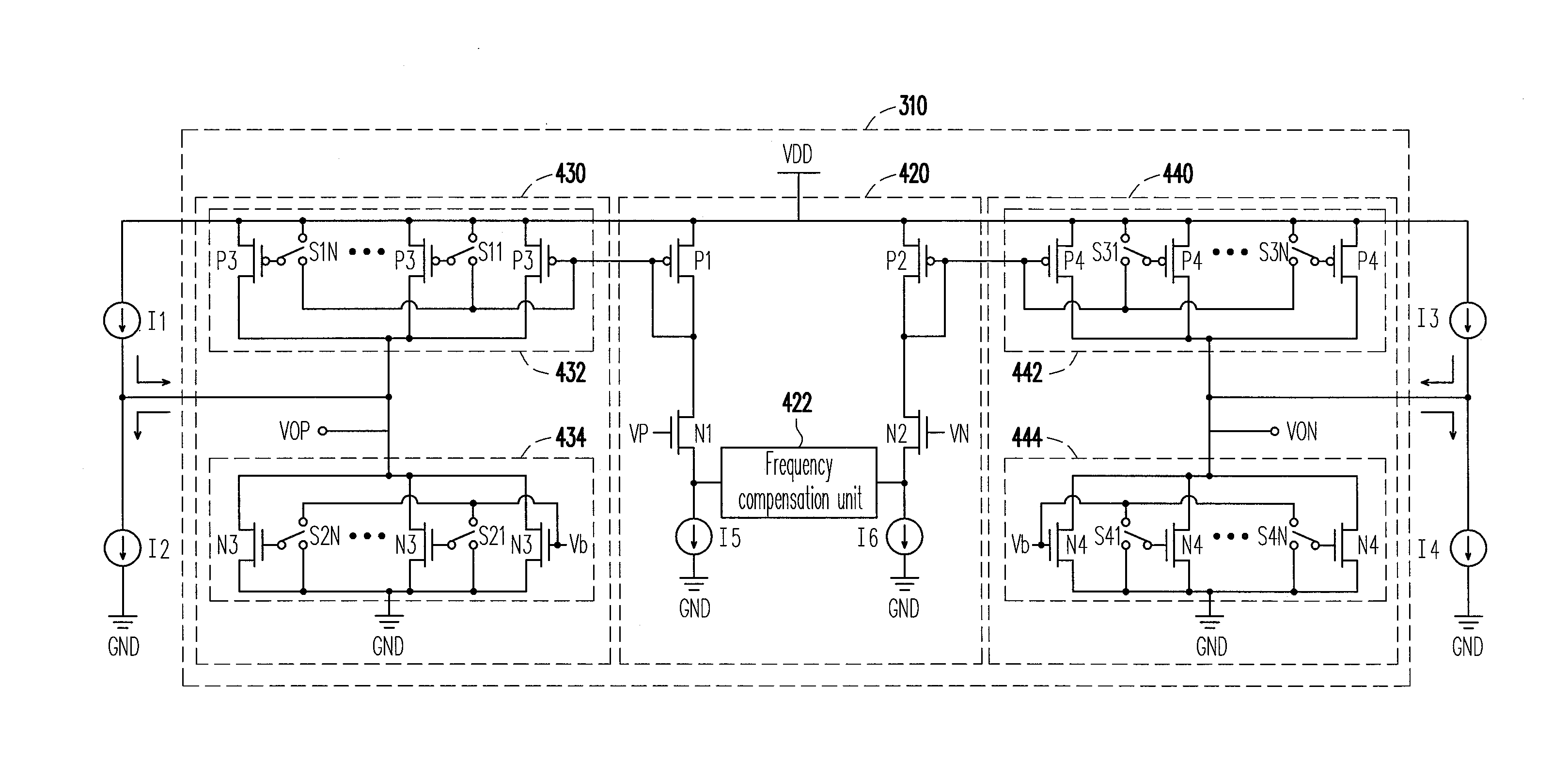
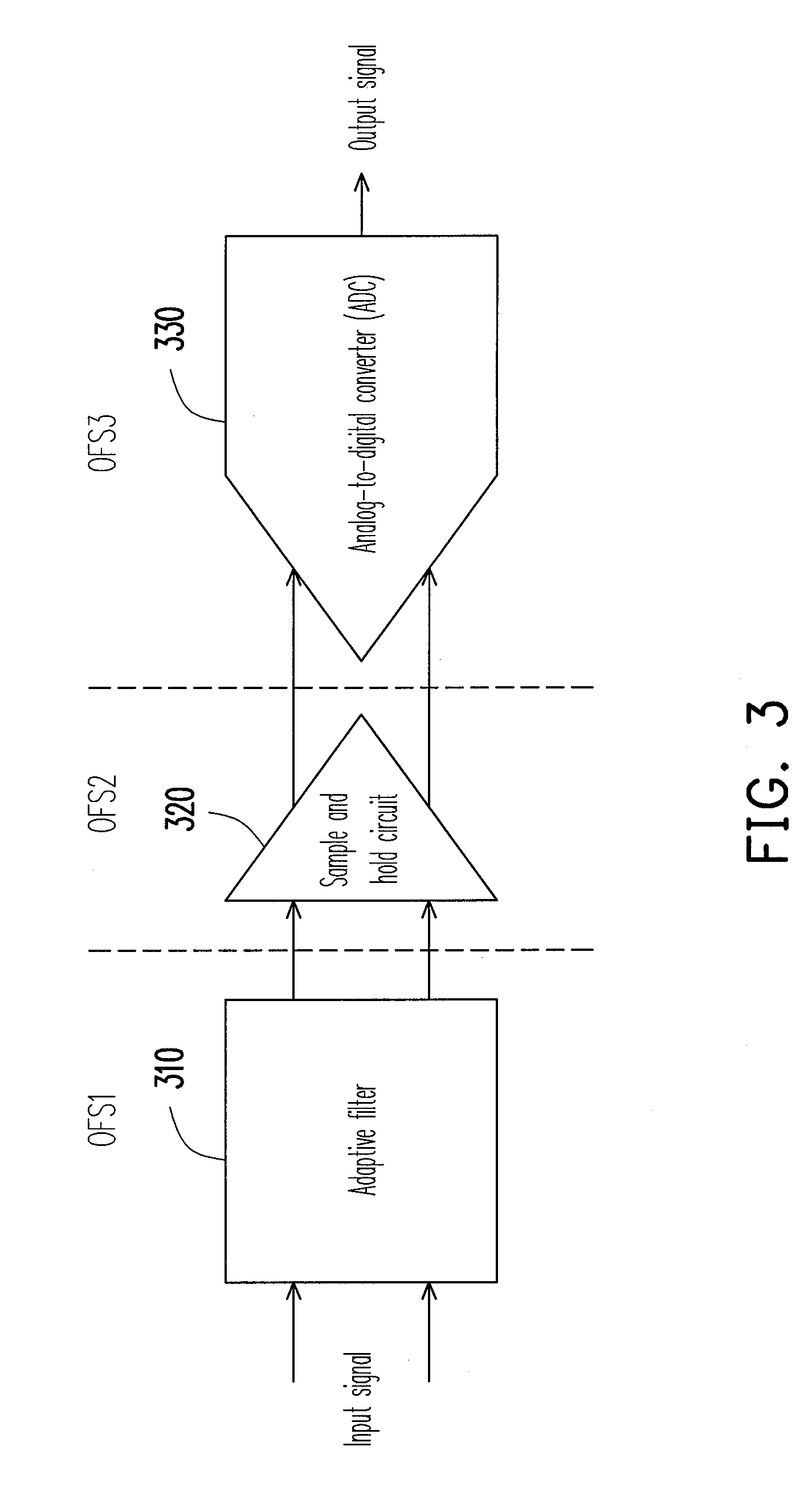
[0026]Referring to FIG. 3, FIG. 3 is a schematic diagram illustrating a front-end circuit of a receiver according to an exemplary embodiment of the invention. The front-end circuit of the receiver generally includes an adaptive filter 310, a sample and hold circuit 320, and an analog-to-digital converter (ADC) 330. The sample and hold circuit 320 is coupled between the adaptive filter 310 and the ADC 330. The adaptive filter 310 is used to restore a high frequency content of a signal. The sample and hold circuit 320 and the ADC 330 are used to convert an analog signal into a digital signal, and provide the digital signal to a digital circuit for processing. The adaptive filter 310 consists of a differential amplifier circuit and a frequency compensation circuit formed by resistors and capacitors.

[0027]Ideally, the adaptive filter 310, the sample and hold circuit 320 and the ADC 330 can all maintain integrity of an input signal without causing a processing error of the digital circui...


PUM


Abstract

A differential offset circuit adapted for an adaptive filter of a receiver front end is provided. The differential offset circuit includes four controllable current sources which are respectively coupled to two differential output terminals of the adaptive filter. The current magnitudes of the controllable current sources are capable of being adjusted according to design requirements so that the differential offset of the adaptive filter is mitigated to avoid that the adaptive filter outputs a distorted signal to affect the accuracy of signal transmission.

Description

CROSS-REFERENCE TO RELATED APPLICATION[0001]This application claims the priority benefit of Taiwan application serial no. 99109863, filed on Mar. 31, 2010. The entirety of the above-mentioned patent application is hereby incorporated by reference herein and made a part of specification.BACKGROUND OF THE INVENTION[0002]1. Field of the Invention[0003]The invention relates to a differential offset calibration circuit. More particularly, the invention relates to a differential offset calibration circuit adapted to mitigating differential offset of an adaptive filter.[0004]2. Description of Related Art[0005]Due to a fabrication process variation, a common gain of a differential amplifier is not zero, which may cause an output differential offset. In case of a relatively great voltage operation range, a tiny differential offset does not affect a normal signal output. As shown in FIG. 1, FIG. 1 is a signal waveform diagram of a differential offset according to a conventional technique. Whe...

Claims


Application Information

Patent Timeline
Patent Type & Authority Applications(United States)
IPC IPC(8): H03L5/00
CPCH03H21/0001
Inventor YI, BIN-WEICHANG, HAO-CHANG
Owner UAB RES FOUND
Why Eureka
Try Eureka