Active continuous-time filter with increased dynamic range in the presence of blocker signals

a continuous-time filter and dynamic range technology, applied in pulse manipulation, frequency selective two-port network, pulse technique, etc., can solve the problems of unsatisfactory signals, unsatisfactory signals, and unsatisfactory signals, so as to achieve the effect of not exceeding the power dissipation or chip area

Inactive Publication Date: 2005-03-29
THE TRUSTEES OF COLUMBIA UNIV IN THE CITY OF NEW YORK +1
View PDF12 Cites 8 Cited by
  • Summary
  • Abstract
  • Description
  • Claims
  • Application Information

AI Technical Summary

Benefits of technology

It is an object of the present invention to process the desired signal and reject blocker signals without excessive power dissipation or chip area. The object is achieved by the introduction of linear resistance elements to the input stage of the active filter. The response of the fixed-value resistors at the input stage remains linear despite the large blocker signals at the input of the filter. The blocker signals are sufficiently attenuated by the input stage so that subsequent MOSFETs are not forced into a non-linear region of operation by the blocker signals. A gain compensation stage is added to the active filter to offset any changes to the gain of the filter caused by the use of both the linear resistance and the variable MOSFET resistance elements.

Problems solved by technology

These undesired signals are called “blockers” and are problematic because the filter that removes them must operate in its linear region to avoid distortion.
Consequently, the strength of the entire range of signals to be processed, including the blocker signal and the desired signal, must be appropriately limited.
This means that the desired signal, which can be orders of magnitude smaller than the blocker signals, will be limited to an extremely small amplitude and can fall below the noise floor of the filter.
Accordingly, it is difficult to implement these filters on an integrated circuit chip, necessitating the use of other technologies which can have penalties in terms of cost and size.
This technique suffers from the disadvantage that large blocker signals present at the input of the active filter may force the MOSFETs that are functioning as variable resistors into a non-linear region of operation, thereby causing distortion in the signals present at the output of the active filter, as previously described.

Method used


Image

  • Active continuous-time filter with increased dynamic range in the presence of blocker signals
  • Active continuous-time filter with increased dynamic range in the presence of blocker signals
  • Active continuous-time filter with increased dynamic range in the presence of blocker signals

Examples


Embodiment Construction

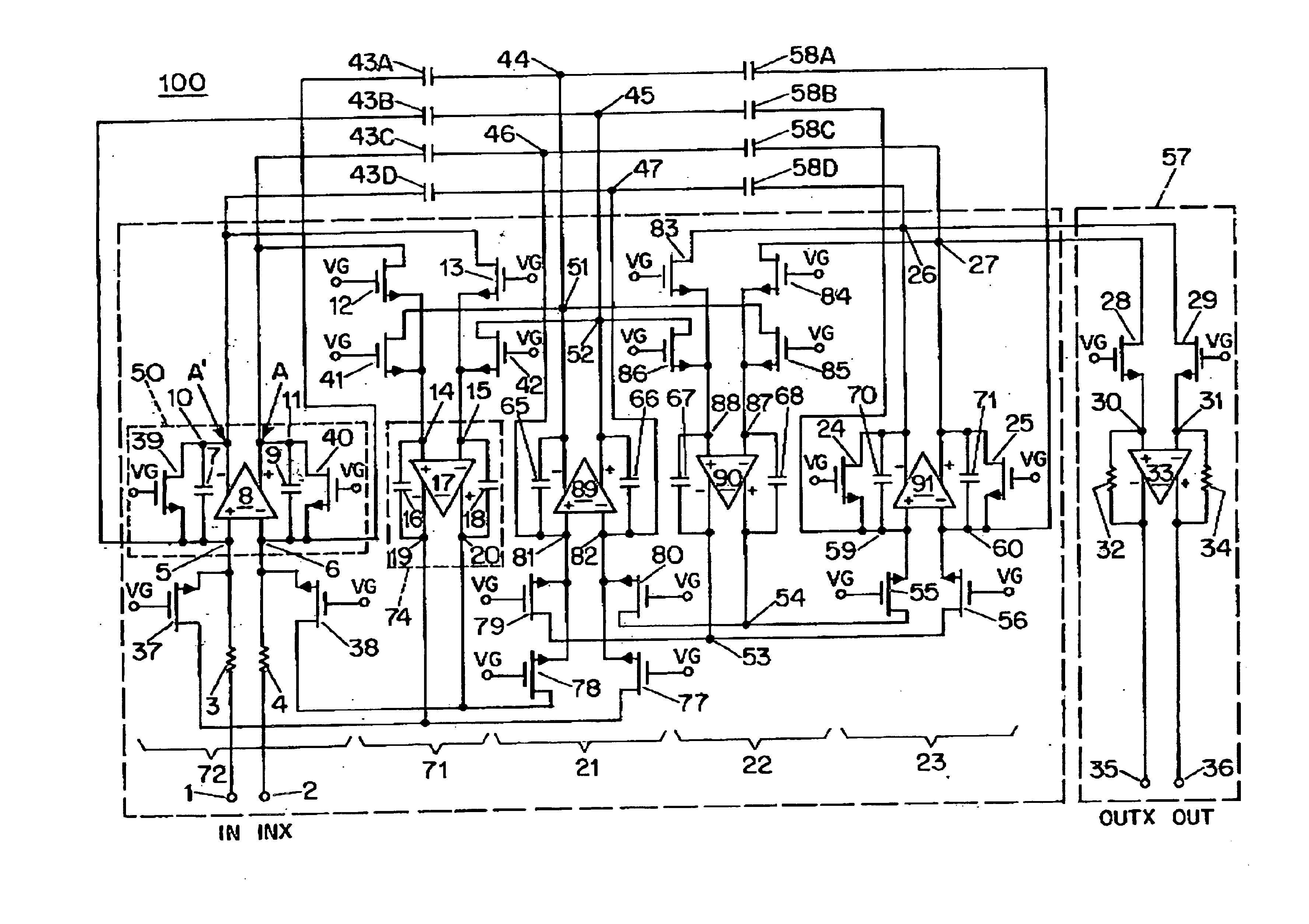
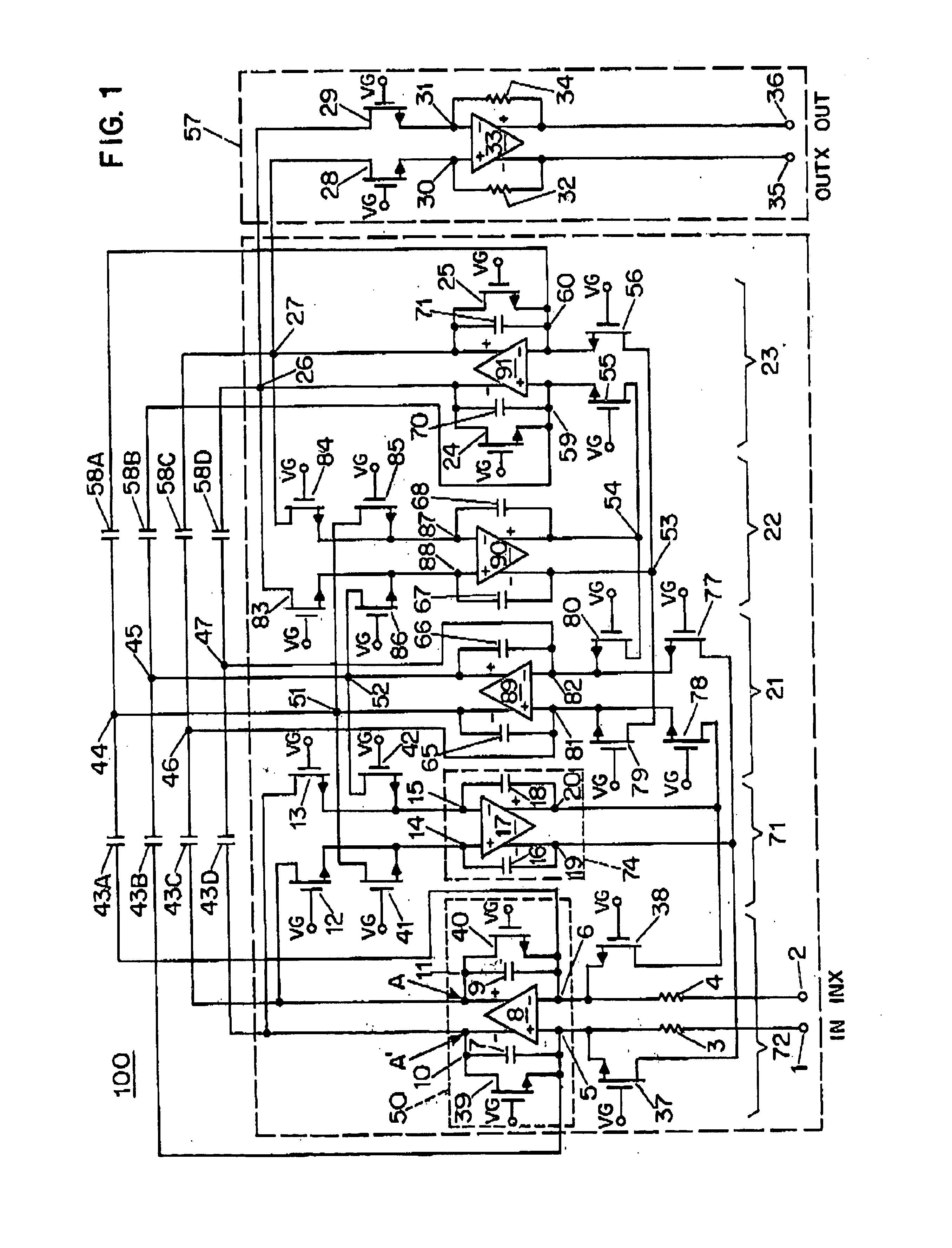
In FIG. 1 an exemplary embodiment of a low-pass filter in accordance with the invention for a direct conversion or zero intermediate frequency receiver is illustrated. The embodiment described has a cut-off frequency of 1.92 MHz, in-band gain of 8.5 dB and out-of-band reaction at 10 MHz of 64 dB.

In operation, fully balanced input signals are applied at input terminals 1 and 2 of the filter. For purposes of this specification and claims, fully balanced means the signals at each input terminal of a circuit are identical in magnitude to one another except have opposite polarity (i.e. the signals are 180° out of phase with respect to one another), and the signals at each output terminal of the circuit are identical to one another except have opposite polarity. The input signals pass through first fully balanced integrator 72 which consists of linear (e.g. fixed value) resistors 3 and 4, fully differential amplifier 8, linear capacitors 7 and 9, variable resistors 37, 38, 39 and 40. Full...


PUM


Abstract

An active filter (100) is disclosed with improved blocker signal rejection characteristics. Linear resistors, such as fixed value resistors (3, 4) are used at the input stage (72) of the filter (100) to suppress any blocker signal. A gain compensation stage (57) is added to the output stage (23) using resistors (24) fabricated with the same technology used to fabricate the input resistors (3, 4) in order to offset any gain changes associated with the input fixed value resistors (3, 4). In an exemplary embodiment, the fixed value resistors (3, 4) are fabricated using polysilicon.

Description

BACKGROUND OF THE INVENTIONRadio communication receivers must receive desired signals at predetermined frequencies while filtering out undesired signals at other frequencies. The undesired signals can have a much larger signal strength than the desired signals. These undesired signals are called “blockers” and are problematic because the filter that removes them must operate in its linear region to avoid distortion. Therefore, the maximum amplitude of all signals applied to the filter input must be limited so that the blocker signals do not cause saturation, clipping or subtler forms of distortion such as intermodulation (a typical measure of which is out-of-band third order input intercept point or IIP3) in the filter. Consequently, the strength of the entire range of signals to be processed, including the blocker signal and the desired signal, must be appropriately limited. This means that the desired signal, which can be orders of magnitude smaller than the blocker signals, will ...

Claims


Application Information

Patent Timeline
IPC IPC(8): H03K5/24H03H11/04H03H11/12H03K5/22H03F3/45H03D7/14H03H11/02H03H11/20
CPCH03D7/1433H03F3/45179H03F3/45511H03H11/1252H03K5/2481H03D7/1408H03D7/1441H03D7/145H03D7/1458H03F3/4508H03D2200/0025H03F2203/45318H03F2203/45352H03F2203/45366H03F2203/45402H03F2203/45418H03F2203/45424H03F2203/45648H03F2203/45652H03F2203/45702H03F2203/45722H03H11/1291H03H11/20
Inventor TSIVIDIS, YANNISYOSHIZAWA, ATSUSHI
Owner THE TRUSTEES OF COLUMBIA UNIV IN THE CITY OF NEW YORK
Why Eureka
Try Eureka