Fuel cell

a fuel cell and polymer technology, applied in the direction of fuel cells, solid electrolyte fuel cells, cell components, etc., can solve the problems of more likely short circuit of electrodes, drop in gas sealability, and power generation capacity loss, and achieve superior power generation capacity, enhanced gas sealability, and tight contact

Inactive Publication Date: 2011-09-29
TOYOTA JIDOSHA KK
View PDF5 Cites 13 Cited by
  • Summary
  • Abstract
  • Description
  • Claims
  • Application Information

AI Technical Summary

Benefits of technology

[0026]As can be understood from the description above, according to a fuel cell of the present invention, it is possible to obtain a fuel cell in which the tightness of contact between the gas flow path layers and the gasket is enhanced and in which gas sealability is enhanced. Further, even in cases where there are manufacturing errors in the gas diffusion layers, it is possible to tolerate them and exert on the membrane electrode assembly pressure from stack formation that is uniform across a plane, and it is possible to obtain a fuel cell with superior power generating capacity.

Problems solved by technology

However, the following problems are present in the above-mentioned conventional art.
As problems stemming from such variations in thickness, for cases where the thickness of the gas diffusion layers after compression is too great and for cases where it is too little, there are such respective specific problems as those given below.
As a result, the contact resistance between the separators d1 and d2 and the gas diffusion layers b1 and b2 is raised, which becomes a cause for a drop in power generating capacity.
Further, due to the fact that the reaction force acting on the protrusion c2 becomes smaller than a desired value, it also becomes a cause for a drop in gas sealability.
In addition, due to the fact that the reaction force acting on the protrusion c2 becomes relatively greater, it becomes more likely for the electrodes to short-circuit, making it more probable that the protrusion c2 would break.
Although it would be fair to say that the performance and gas sealability of each cell constituting the fuel cell rest on the above-mentioned variations in the gas diffusion layers, on the other hand, it would be extremely difficult to secure the desired sealability while tolerating the above-mentioned variations.
In addition, if a gasket having variations per portion thereof as mentioned above were used, there would be variations in pressure when the fuel cell is integrated as a stack, that is, in the pressure acting on the membrane electrode assembly, which would inhibit uniform power generation across the plane, directly leading to a drop in the power generating capacity of the fuel cell.

Method used


Image

  • Fuel cell
  • Fuel cell
  • Fuel cell

Examples


Embodiment Construction

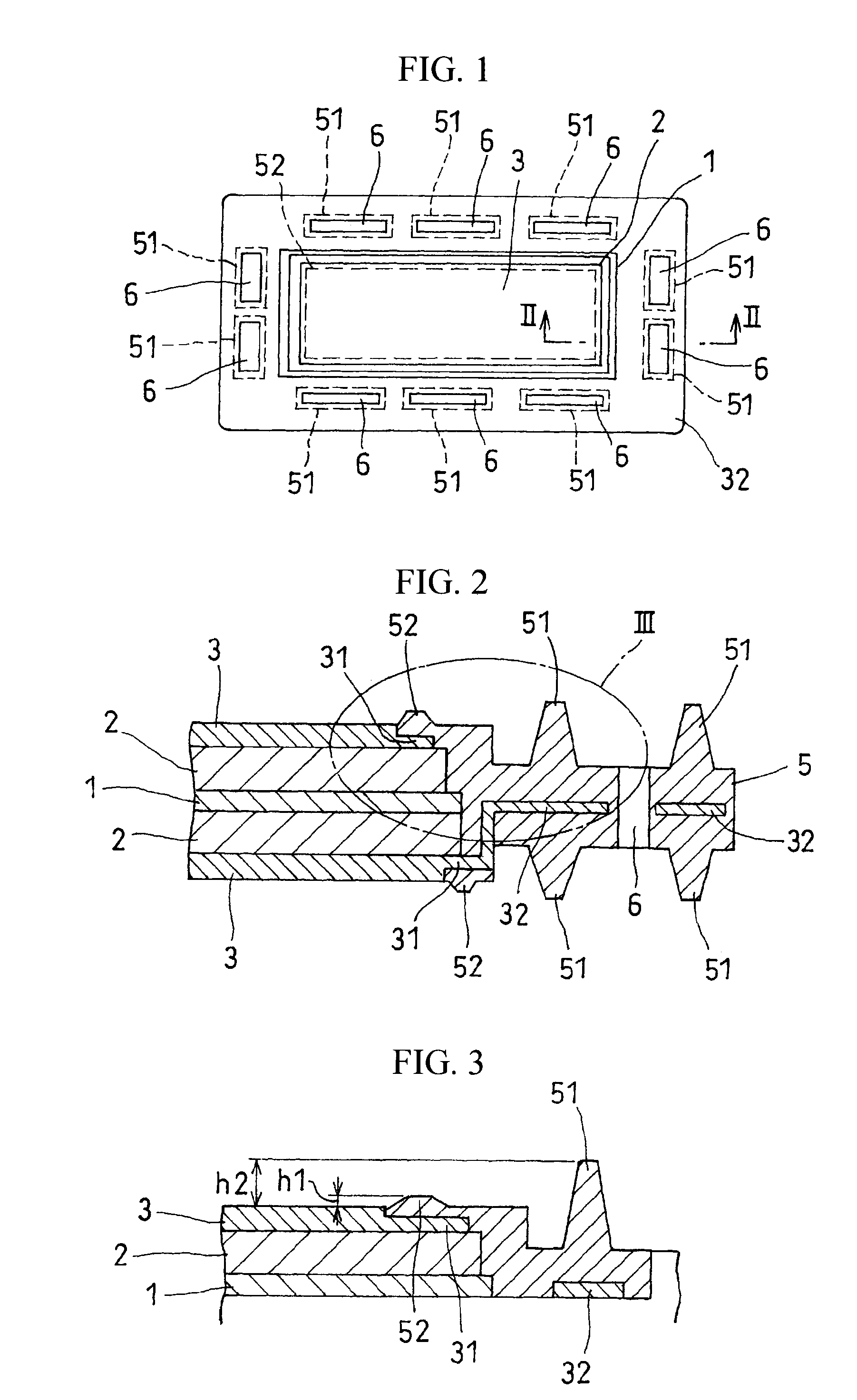
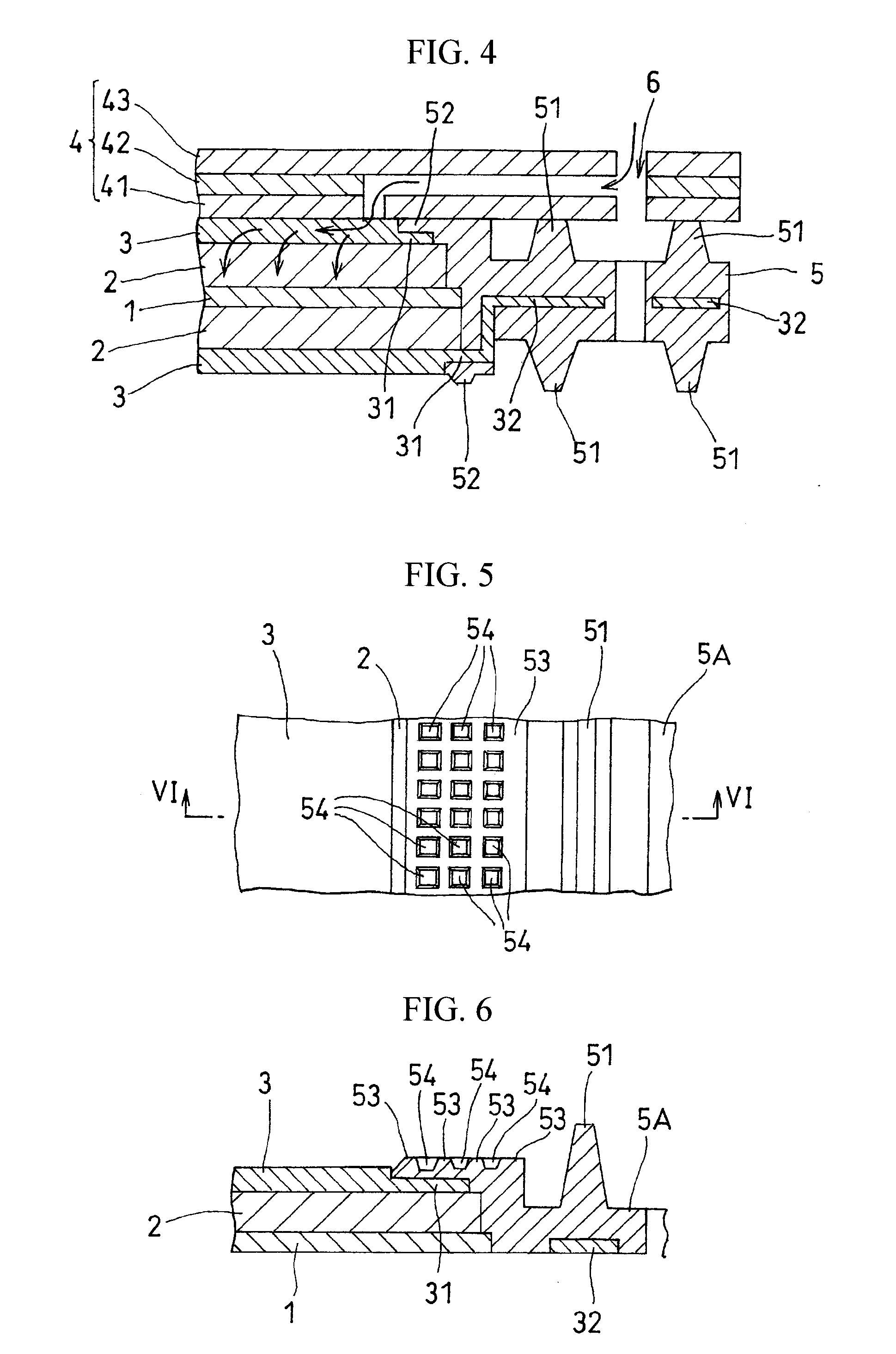
[0038]Embodiments of the present invention are described below with reference to the drawings. FIG. 1 is a plan view of a cell structure in which a membrane electrode assembly is sandwiched by gas flow path layers. FIG. 2 is a fragmentary view taken along arrows II-II in FIG. 1. FIG. 3 is an enlarged view of portion III in FIG. 2. FIG. 4 is a sectional view showing a state where a separator on the cathode side is attached to the sectional view in FIG. 2. It is noted that while the linear seal protrusions (second seal protrusions) shown in the drawings are lower in height than the seal protrusions (first seal protrusions) around the manifold, the two may naturally be of the same height as well.

[0039]The cell structure shown in FIGS. 1 and 2 comprises a membrane electrode assembly (MEA), which formed from an electrolyte membrane 1 (MEA) that is an ion exchange membrane and gas diffusion layers 2, 2 (GDL) on the anode side and the cathode side that sandwich it, and gas flow path layers...


PUM


Abstract

There is provided a fuel cell having a seal structure that has high gas sealability and, further, is capable of supplying gas to a membrane electrode assembly without being path-cut even if there are conventional processing errors (variations) in the gasket. With respect to a gasket 5 provided at the periphery of the membrane electrode assembly, a first seal protrusion 51 is formed around a manifold 6. A notch 31 is formed at an end portion of a gas flow path layer 3. An end portion of the gasket 5 blocks the notch 31 and has at least one second seal protrusion 52 protruding from the surface of the gas flow path layer 3 and having a height of the same level as or less than the first seal protrusion 51. A separator 4 is in contact with the gas flow path layer 3 in a posture where the first seal protrusion 51 and the second seal protrusion 52 are compressed. At least one linear seal structure is formed by the second seal protrusion 52 and the separator 4.

Description

TECHNICAL FIELD[0001]The present invention relates to solid polymer fuel cells.BACKGROUND ART[0002]In a cell of a solid polymer fuel cell, a membrane electrode assembly (MEA) is formed from an ion-permeable electrolyte membrane, and an anode electrode layer and a cathode electrode layer sandwiching the electrolyte membrane, and a unit cell is formed by disposing separators on the outer side thereof. It is noted that there is also a form in which a membrane electrode assembly (MEGA: Membrane Electrode & Gas Diffusion Layer Assembly) is formed by providing gas diffusion layers (GDLs) for promoting gas flow and enhancing collection efficiency on the outer side of the electrode layers, and in which separators are disposed on the outer side of the gas diffusion layers. This separator functions as a gas flow path by defining a cell space and having a concavo-convex form, and is even equipped with a collection function. However, with respect to modern cell structures, there have also been ...

Claims


Application Information

Patent Timeline
IPC IPC(8): H01M8/10H01M8/04H01M2/14
CPCH01M8/0273H01M8/0276Y02E60/50H01M2008/1095H01M8/242H01M8/0258H01M8/0271
Inventor IIZUKA, KAZUTAKAKATO, CHISATO
Owner TOYOTA JIDOSHA KK
Why Eureka
Try Eureka