Proton exchange membrane fuel cell stack

a technology applied in the field of protons and fuel cells, can solve the problems of difficult downsizing of the fuel cell system, and achieve the effects of thinning the fuel cell stack, and reducing the number of cooling cells

Inactive Publication Date: 2011-09-22
HITACHI LTD
View PDF6 Cites 3 Cited by
  • Summary
  • Abstract
  • Description
  • Claims
  • Application Information

AI Technical Summary

Benefits of technology

[0011]The present invention is provided in view of these tasks, and an object of the present invention is to provide a fuel cell stack capable of downsizing the fuel cell stack by an easy and simple cooling structure.
[0014]According to the present invention, by the following arrangement where a reactant gas flow fields such as the fuel gas flow field and the oxidant gas flow field is constituted by the porous media as porous media flow fields, and where liquid water is supplied mixedly together with the oxidant gas into the porous media flow field, it is possible to perform cooling by means of latent heat of evaporation in the porous media field, and thereby to reduce the number of cooling cells and realize a thinning of the fuel cell stack. In detail, the porous media flow field's surface opposing to the membrane electrode assembly (MEA) can contact with almost surface of the cathode (electrode catalysts) through fine pores of the porous medium, the reaction can be effected over the almost entire faces of the electrode catalysts. Further, since the liquid water is caused mixed into the oxidant gas, and performs cooling by means of latent heat of evaporation, the number of cooling cells can be reduced, and a thinning of the fuel cell stack is enabled.

Problems solved by technology

However, the fine water drop formation since requires injecting water in high pressure, it is difficult to downsize the fuel cell system because of an increase of such as auxiliary equipments and driving power.

Method used


Image

  • Proton exchange membrane fuel cell stack
  • Proton exchange membrane fuel cell stack
  • Proton exchange membrane fuel cell stack

Examples


embodiment 1

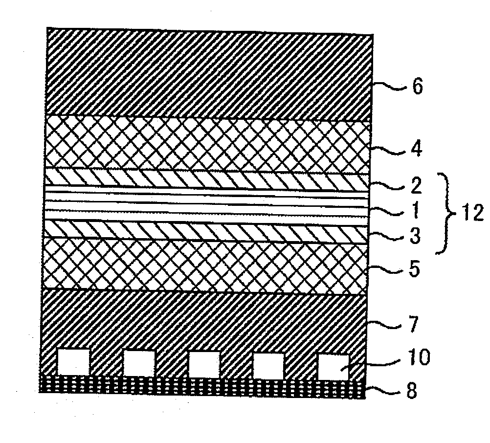
[0020]FIG. 1 is a sectioned schematic drawing of a unit cell applied for a first embodiment of a unit cell applied for a fuel cell stack according to the present invention, wherein the section drawing is illustrated along a direction perpendicular to a reactant gas flow direction in the fuel cell. The unit cell is comprised of: a membrane electrode assembly (MEA) 12 constituted by a solid polymer electrolyte membrane 1, an anode 2 as an electrode catalyst layer and a cathode 3 as an electrode catalyst layer, the anode 2 and cathode 3 being disposed on both sides of the solid polymer electrolyte membrane 1 respectively; gas diffusion layers 4 and 5, porous media flow fields 6 and 7 as an anode side-fuel flow field and a cathode side-oxidant gas flow field, and a porous bipolar plate 8 being disposed on the outsides of the electrode catalyst layers 2 and 3 respectively. The gas diffusion layers can be sometimes omitted. Further, although not illustrated, the unit cell is provided with...

embodiment 2

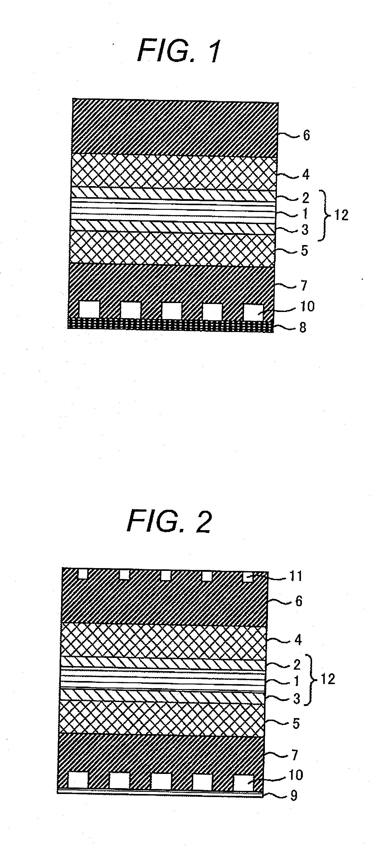
[0034]FIG. 2 is a sectioned schematic drawing of a second embodiment of a unit cell applied for a fuel cell stack according to the present invention, wherein the section drawing is illustrated along a direction perpendicular to a reactant gas flow direction in the fuel cell. In the second embodiment, almost the arrangement of the fuel cell is the same as that of the first embodiment according to the present invention and differences from the first embodiment are as follow. Namely, first of all, in addition to the cathode side-channels 10 in the cathode side-porous media field, the anode side-porous media flow field 6 (fuel gas flow field) is also provided with anode side-channels 11 on a surface opposing to a bipolar plate 9 of another unit cell stacked on the unit cell. Next, each bipolar plate 9 of the present embodiment's fuel cell stack is made of a metallic flat plate.

[0035]The bipolar plate 9 is constituted by a metallic plate such as a pure metal and an alloy each having thic...


PUM

PropertyMeasurementUnit
stack-operating temperatureaaaaaaaaaa
diameteraaaaaaaaaa

Abstract

A proton exchange membrane fuel cell stack comprises a plurality of stacked unit cells, the unit cells each including: a membrane electrode assembly; an anode side-conductive gas diffusion layer and an anode side-fuel gas flow field to feed a fuel gas to an anode of the membrane electrode assembly; and a cathode side-conductive gas diffusion layer and a cathode side-oxidant gas flow field to feed an oxidant gas to a cathode of the membrane electrode assembly; and a bipolar plate for separating between the anode side-fuel flow field and the cathode side-oxidant gas flow field. Then, the fuel gas flow field and the oxidant gas flow field are constituted by respective porous media flow fields each which is a conductive porous medium, and the porous media flow field for the oxidant gas flow field is configured so that liquid water is supplied mixedly together with the oxidant gas thereto.

Description

CLAIM OF PRIORITY[0001]The present application claims priority from Japanese application serial no. 2010-060105 filed on Mar. 17, 2010, the contents of which are hereby incorporated by reference into this application.FIELD OF THE INVENTION[0002]The present invention relates to a proton exchange membrane fuel cell stack for generating electrical energy through chemical reaction between hydrogen and oxygen.BACKGROUND ART[0003]A proton exchange membrane fuel cell stack comprises a plurality of stacked unit cells each including a membrane electrode assembly (MEA). The MEA is comprised of a solid polymer electrolyte membrane, a fuel electrode catalyst layer (herein below will be also called as anode), and an oxidant electrode catalyst layer (herein below will be also called as cathode), wherein the anode and cathode are arranged on both sides of the solid polymer electrolyte membrane respectively. Both sides of the MEA are provided with gas diffusion layers consisted of a porous carbon m...

Claims


Application Information

Patent Timeline
Patent Type & Authority Applications(United States)
IPC IPC(8): H01M8/24H01M8/04
CPCH01M8/023H01M8/04059Y02E60/50H01M2008/1095H01M8/04126
Inventor KOZAKAI, MASAYAOKUSAWA, TSUTOMU
Owner HITACHI LTD
Why Eureka
Try Eureka