Heat-dissipating fan

a technology of heat dissipating fans and fans, which is applied in the direction of magnetic circuit rotating parts, piston pumps, magnetic circuit shapes/forms/construction, etc., can solve the problems of insatiable, difficult to achieve a light, compact design, etc., and achieve the effect of reducing the axial height simplifying the structure of the heat dissipating fan

Active Publication Date: 2013-04-16
SUNONWEALTH ELECTRIC MACHINE IND
View PDF15 Cites 9 Cited by
  • Summary
  • Abstract
  • Description
  • Claims
  • Application Information

AI Technical Summary

Benefits of technology

[0008]The present invention solves this need and other problems in the field of miniaturization of heat-dissipating fans by providing, in a first aspect, a heat-dissipating fan including a shaft seat. A coil base is coupled to the shaft seat. The coil base includes a base portion and a coil unit coupled to the base portion. The base portion includes a connection port electrically connected to the coil unit. An impeller includes a hub and a permanent magnet. A shaft is coupled to the hub and rotatably coupled to the shaft seat about an axis. The permanent magnet is coupled to the hub and aligned with the coil unit. The connection port can be electrically connected to a drive circuit by a connection wire. Since the coil base does not include electronic elements of the drive circuit, the axial height of the heat-dissipating fan is reduced, and the structure of the heat-dissipating fan is simplified.
[0009]In a preferred form, the shaft seat includes a fixed portion and a coupling portion formed on a side of the fixed portion. The shaft is rotatably coupled to the coupling portion. The base portion includes an outer layer formed on a face of the base portion. The coil unit is formed on a side of the outer layer, and the coil unit is intermediate the outer layer and the fixed portion of the shaft seat along the axis. The axial height of the heat-dissipating fan can be further reduced.
[0010]In preferred forms, the base portion of the coil base includes first and second faces spaced along the axis. An outer layer is formed on the first face. A bottom layer is formed on the second face, and the coil unit is intermediate the first and second faces along the axis. The axial height of the heat-dissipating fan can be further reduced.

Problems solved by technology

As a result, it is difficult to achieve a light, compact design of the heat-dissipating fans and, thus, it is difficult to mount the heat-dissipating fans in miniature electronic devices or equipment.
However, the results are not satisfactory. FIG. 1 shows a conventional heat-dissipating fan 80 including a housing 81, a control unit 82, a stator 83, and an impeller 84.
Overall, the effect in reduction of the axial height is limited.
However, the drive circuit on the control circuit board 92 still has certain heights in the axial direction, causing limitation to further reduction in the overall axial height of the heat-dissipating fan 90 when the circuit board 92 is mounted on the base 912.
As a result, it is difficult to achieve a light, compact design of the heat-dissipating fan 90 and, thus, it is difficult to mount the heat-dissipating fan 90 in miniature electronic devices or equipment.

Method used


Image

  • Heat-dissipating fan
  • Heat-dissipating fan
  • Heat-dissipating fan

Examples


Embodiment Construction

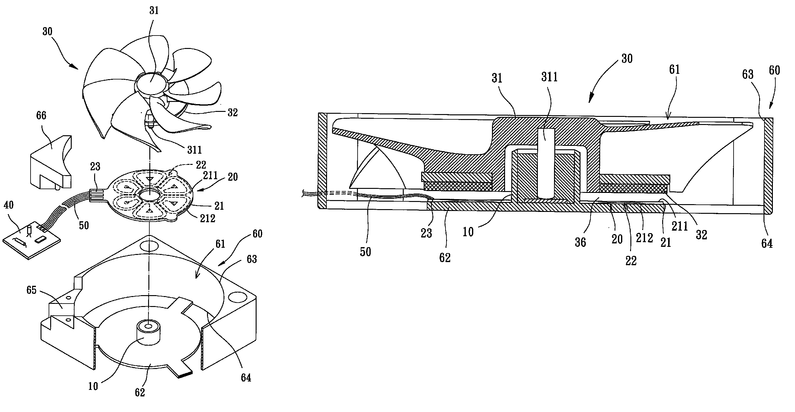
[0031]A heat-dissipating fan according to the preferred teachings of the present invention is shown in FIGS. 4-10 of the drawings. In the preferred form shown in FIGS. 4-9, the heat-dissipating fan includes a shaft seat 10, a coil base 20, and an impeller 30. The shaft seat 10 includes a fixed portion 11 and a coupling portion 12 formed on a side of the fixed portion 11. The fixed portion 11 can be directly coupled in a desired location of any electronic device or equipment or of an object requiring dissipation of heat.

[0032]In the preferred form shown in FIGS. 4-9, the coil base 20 includes a base portion 21 and a coil unit 22. The base portion 21 is preferably a printed circuit board and has opposite first and second faces spaced along an axis. The coil unit 22 can be formed by layout or other suitable provisions to be integrally formed with the base portion 21. Preferably, the coil unit 22 does not protrude beyond the first and second faces of the base portion 21, to effectively ...


PUM


Abstract

A heat-dissipating fan includes a shaft seat. A coil base is coupled to the shaft seat. The coil base includes a base portion and a coil unit coupled to the base portion. The base portion includes a connection port electrically connected to the coil unit. The connection port is connected to a drive circuit. An impeller includes a hub and a permanent magnet. A shaft is coupled to the hub and rotatably coupled to the shaft seat about an axis. The permanent magnet is coupled to the hub and aligned with the coil unit. Since the coil base does not include electronic elements of the drive circuit, the axial height of the heat-dissipating fan is reduced, and the structure of the heat-dissipating fan is simplified.

Description

BACKGROUND OF THE INVENTION[0001]1. Field of the Invention[0002]The present invention relates to a heat-dissipating fan and, more particularly, to a heat-dissipating fan with a reduced axial height and with a reduced volume.[0003]2. Description of the Related Art[0004]Miniaturization is the trend of electronic products. Currently available heat-dissipating fans generally include a housing, a stator and an impeller. The stator includes a stator core, a coil unit, and a circuit board. The stator comprised of the stator core, the coil unit, and the circuit board limits reduction in the overall axial height of the heat-dissipating fans. As a result, it is difficult to achieve a light, compact design of the heat-dissipating fans and, thus, it is difficult to mount the heat-dissipating fans in miniature electronic devices or equipment.[0005]Efforts have been made in reducing the axial height of the heat-dissipating fans by reducing the axial height and volume of the stator. However, the r...

Claims


Application Information

Patent Timeline
Patent Type & Authority Patents(United States)
IPC IPC(8): F04B35/04H02K21/12H02K1/22
CPCF04D25/0653
Inventor HORNG, ALEX
Owner SUNONWEALTH ELECTRIC MACHINE IND
Why Eureka
Try Eureka