Energy storage vessel, systems, and methods

Inactive Publication Date: 2011-09-22
BELL INDEPENDENT POWER CORP
View PDF7 Cites 46 Cited by
  • Summary
  • Abstract
  • Description
  • Claims
  • Application Information

AI Technical Summary

Benefits of technology

[0023]In accordance with the present disclosure, the problem of containing a large mass of molten salt, which undergoes repeated extreme thermal cycling in a thermal energy storage system is solved by providing a vessel comprising a bottom wall joined to a surrounding side wall, and an inner liner disposed within the bottom wall and side wall and comprising an inner liner bottom and an inner liner side wall. One aspect of the inner liner bottom and side wall is that they are configured to repeatedly expand and contract during the thermal cycling of the storage system in a manner that avoids stress concentrations within the liner, which could otherwise cause fractures and leaks in the liner. The liner bottom and side wall are both comprised of means for expanding radially outwardly when heated, and contracting radially inwardly when cooled, without producing stress concentrations.
[0025]The inner liner contained within the vessel is constructed so as to be able to expand and contract under the loading thereof with the molten salt, and in particular, due to the thermal expansion and contraction caused by contact with the molten salt at temperatures up to about 750° F. During thermal cycling, the radial and inner flexible joints of the liner bottom and the lateral flexible joints of the liner side wall flex and accommodate the thermal expansion and contraction of the sector shaped plates and arcuate panels, so as to prevent localized stress concentrations in the liner. The central plate may be circular, or the central plate may be a polygon. The number of sides of the polygon may be equal to the number of sector-shaped plates. The number of radially arranged sector-shaped plates may be between three and twelve, or more, depending upon the size of the vessel. A flexible joint which joins a sector shaped plate at a radial portion of its perimeter to a radial portion of the perimeter of an adjacent plate may be comprised of an arcuate shaped member formed and joined to the adjacent plates.
[0028]The vessel may further include thermal insulation disposed between the bottom wall of the vessel and the inner liner bottom. The bottom thermal insulation may be comprised of a plurality of support members of a first insulating material interspersed within a second insulating material. The support members of the first insulating material provide structural support to the liner bottom, thereby enabling the second insulating material to have a higher R-value without needing to provide significant structural support. Hence the combination of the first and second insulating materials provided in this manner solves the problem of having insulation that has the required structural strength and the required high R-value insulating capability. In embodiments in which an outer liner is provided, the thermal insulation is disposed between the bottom wall of the vessel and the outer liner bottom.

Problems solved by technology

Unfortunately, when the sun or wind is not available, such solutions are not producing any power.
Similar issues arise for wind turbines during calm weather.
While this system takes advantage of a vertical temperature gradient within the thermocline tank to enable simplification to a single tank, challenges with respect to the pumping, valving, and delivery of molten salt through a complex network of piping to the solar field, and to the power generator remain present.
The handling of heat transfer fluid by standard pumps, valves and piping is much simpler than the equivalent handling of a molten inorganic salt, which is corrosive, and which is abrasive if some portion of solid phase salt (crystals) is present, and which can solidify in the pumps, valves, and piping at temperatures lower than 400° F., thus requiring a disruptive thawing process step to restart the system.
This simplification notwithstanding, the problems of containing the molten salt, and transferring thermal energy to and from it are significant, particularly at the scale needed by a public utility for an economically viable thermal energy storage process.

Method used


Image

  • Energy storage vessel, systems, and methods
  • Energy storage vessel, systems, and methods
  • Energy storage vessel, systems, and methods

Examples


Embodiment Construction

[0059]For a general understanding of the present invention, reference is made to the drawings. In the drawings, like reference numerals have been used throughout to designate identical elements.

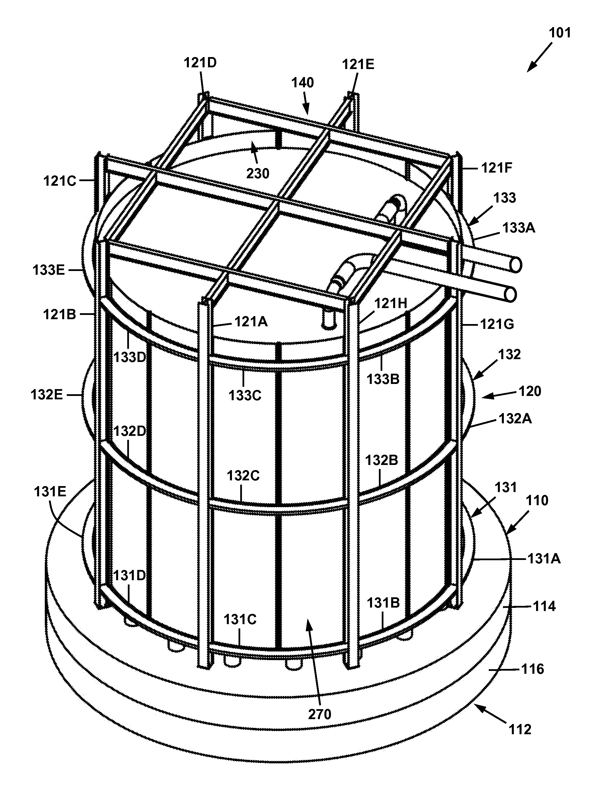
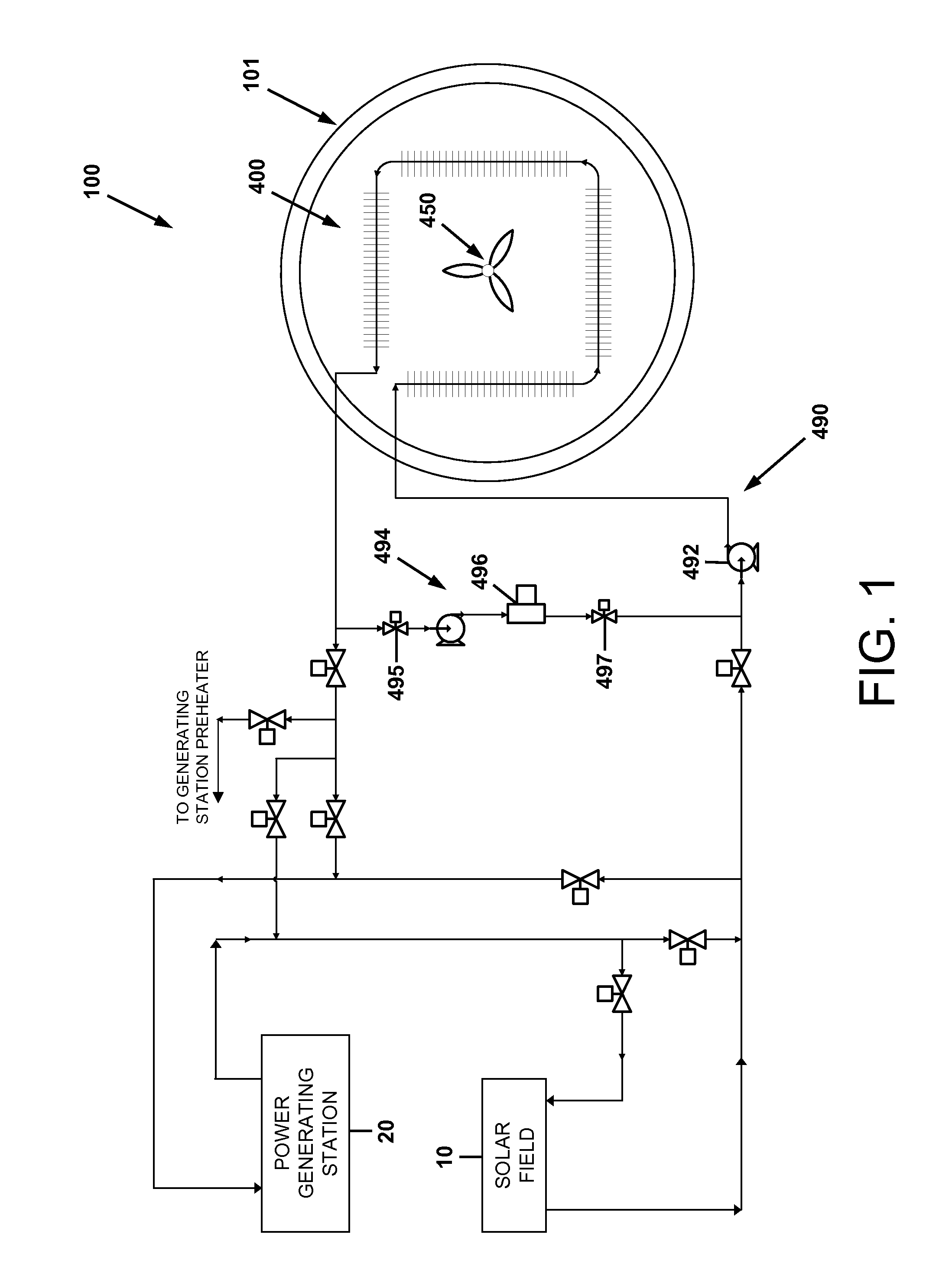
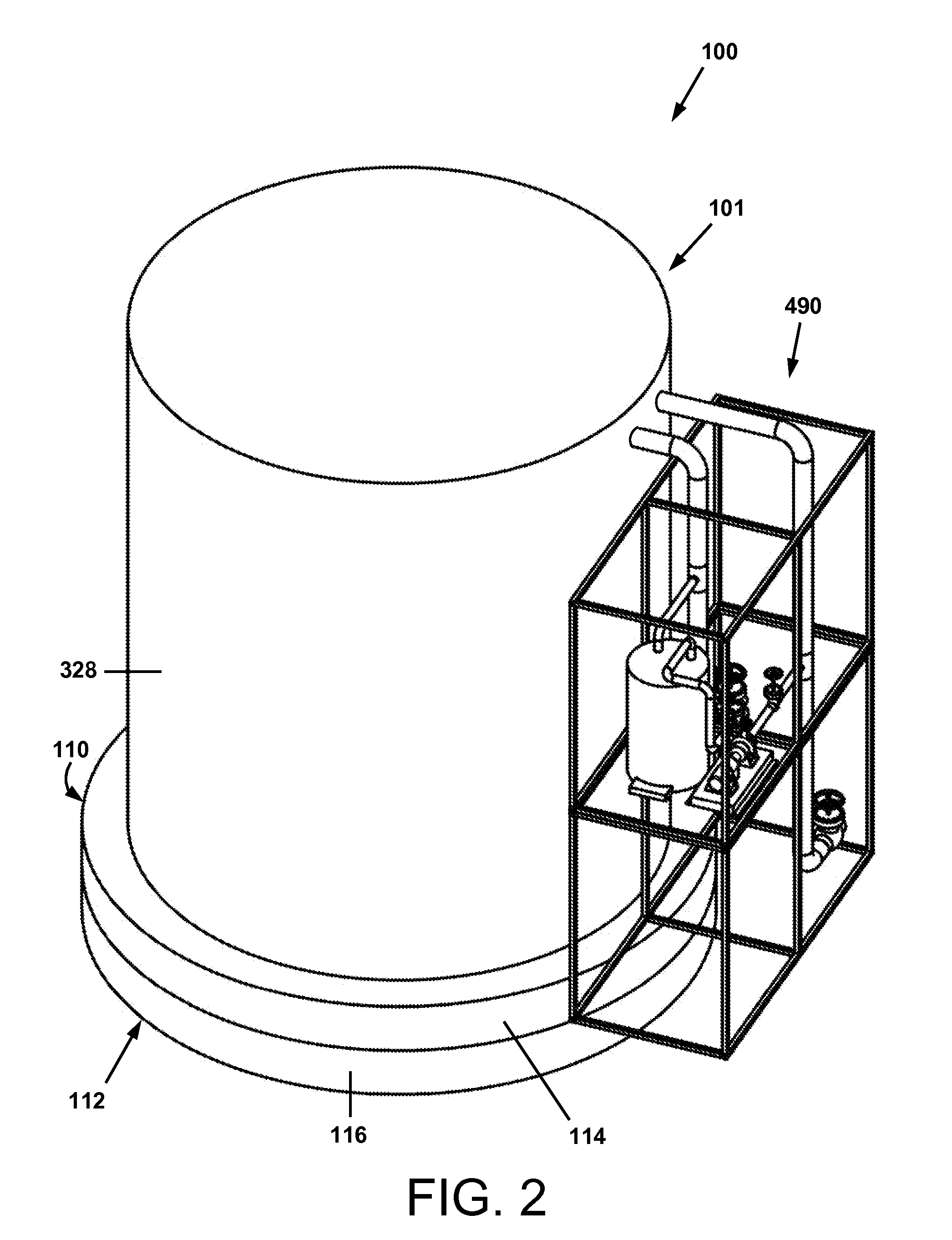
[0060]FIG. 1 is a schematic illustration of a thermal storage system and method in accordance with the present disclosure. The thermal energy storage system 100 is comprised of a containment vessel 101, which contains a heat exchanger or an array 400 of heat exchangers immersed in a molten salt. The system 100 is further comprised of a liquid transfer unit 490 (that may be of a modular design), which circulates a heat transfer fluid through the heat exchangers during operation of the system 100. The liquid transfer unit 490 is comprised of liquid piping, various switching and control valves, a pump 492, and a pressure relief tank (not shown). The liquid transfer unit 490 may further include a heater loop 494 comprising an oil heater 496 and an expansion tank (not shown) for heating and circul...


PUM


Abstract

A vessel for a thermal energy storage system comprising a bottom wall joined to a surrounding side wall, and an inner liner disposed within the bottom wall and side wall and comprising an inner liner bottom and an inner liner side wall. One aspect of the inner liner bottom and side wall is that they are configured to repeatedly expand and contract during the thermal cycling of the storage system. A thermal energy storage system comprising the containment vessel and an array of heat exchangers is also disclosed. The heat exchangers are disposed in the vessel, and arranged so as to enclose a volume within the vessel. Each of the heat exchangers is suspended by a suspension assembly. The assembly may be comprised of a central support hanger, a spring loaded upper hanger, and a lower hanger.

Description

CROSS-REFERENCE TO RELATED PATENT APPLICATIONS[0001]This application claims priority from U.S. provisional patent Application No. 61 / 314,313, filed Mar. 16, 2010, the disclosure of which is incorporated herein by reference. This application is also related to the following copending commonly owned United States patent applications: application Ser. No. 12 / 033,604 of Geiken et al., filed Feb. 19, 2008; application Ser. No. 12 / 172,673 of Flynn et al., filed Jul. 14, 2008; and application Ser. No. 12 / 842,203 of Bell et al., filed Jul. 23, 2010. The disclosures of these United States patent applications are incorporated herein by reference in their entireties.BACKGROUND[0002]1. Field of the Invention[0003]The inventions disclosed herein relate generally to energy storage and, more particularly, to thermal energy storage systems and methods thereof.[0004]2. Description of Related Art[0005]Worldwide, there are ever-growing demands for electricity due to increasing populations, technology ...

Claims


Application Information

Patent Timeline
IPC IPC(8): B65D88/06B65D90/04B65D81/38
CPCF28D1/0426F28D1/05333F28D20/0034F28D20/021F28D2020/0047F28F2265/26F28F9/002F28F13/125Y02E60/142Y02E60/145F28F2270/00F28F1/14Y02E60/14
Inventor BELL, JOHN P.BELL, JR., JOSEPH M.BOWER, MICHAEL S.WALTER, GERARD C.
Owner BELL INDEPENDENT POWER CORP
Why Eureka
Try Eureka