High pressure water spray plastic pipe replacement apparatus and method

a technology of plastic pipe replacement and high pressure water spray, which is applied in the direction of mechanical equipment, pipes/joints/fittings, pipe elements, etc., can solve the problems of polybutylene polymer pipes that fail, degrade, rupture or damage, and need replacement, so as to reduce the friction force of replacement pipes

Inactive Publication Date: 2011-08-25
MR GERALD STEVEN SUTTON
View PDF3 Cites 13 Cited by
  • Summary
  • Abstract
  • Description
  • Claims
  • Application Information

AI Technical Summary

Benefits of technology

[0019]The tool is pulled through the prior existing pipe by way of a flexible cable attached to a winch, come along or other pulling devise. The flexible cable attaches to the nose section of the tool and the replacement pipe attaches to the opposite end of the tool. The shape of the nose section allows it to be pulled through bends in the buried pipe and remain substantially centered inside the prior existing pipe. The knife blades split the pipe as the tool is pulled through the prior existing pipe. The cone section expands the prior existing pipe out and into the surrounding soil to allow room for the replacement pipe to be pulled into place in a nonbinding manner. High pressure water exits the nozzles on the main body of the tool in a substantially forward direction which er...

Problems solved by technology

For various reasons these pipes fail, degrade, rupture or are damaged in some manner and need to be replaced.
Polymeric pipes made of polybutylene for example are known to fail and need replacement after prolonged contact with chlorinated water.
This method can be very costly and results in damage to yards, landscaping, sidewalks, driveways and other structures which must be removed during excavation.
Trenchless methods also exist which involve limited excavation, but the equipment used in these methods generate very high forces which are transferred from the equipment into the surrounding environment.
As a result these methods can damage existing structures on each end of the pipeline being replaced.
If the split pipe and surrounding soil are not expanded out sufficiently by the mole, the compressive forces exerted Upon the replacement pipe by the surrounding soil can damage the replacement pipe or disconnect it from the mole.
Equipment capable of generating the required force are large, heavy, bulky and expensive.
Because of its size and or weight it is impractical to place this equipment in basements, crawl spaces or inside most buildings and homes.
Because of the size of the impact devise and the size of supply lines to provide compressed air to operate the impact devise this method is not suitable for smaller diameter pipes, where the mole is not large enough to house an adequately sized impact devise or the replacement pipe is not large enough to contain the required supply line to operate the impact devise.
Other disadvant...

Method used


Image

  • High pressure water spray plastic pipe replacement apparatus and method
  • High pressure water spray plastic pipe replacement apparatus and method
  • High pressure water spray plastic pipe replacement apparatus and method

Examples


Embodiment Construction

[0026]The plastic pipe replacement tool which is also referred to as the mole 21 is made of metal such as stainless steel and consists of as a nose section 4, expansion cone section 11, hose barb section 14, nozzles 12 and cutting blades 6 as shown in FIG. 1.

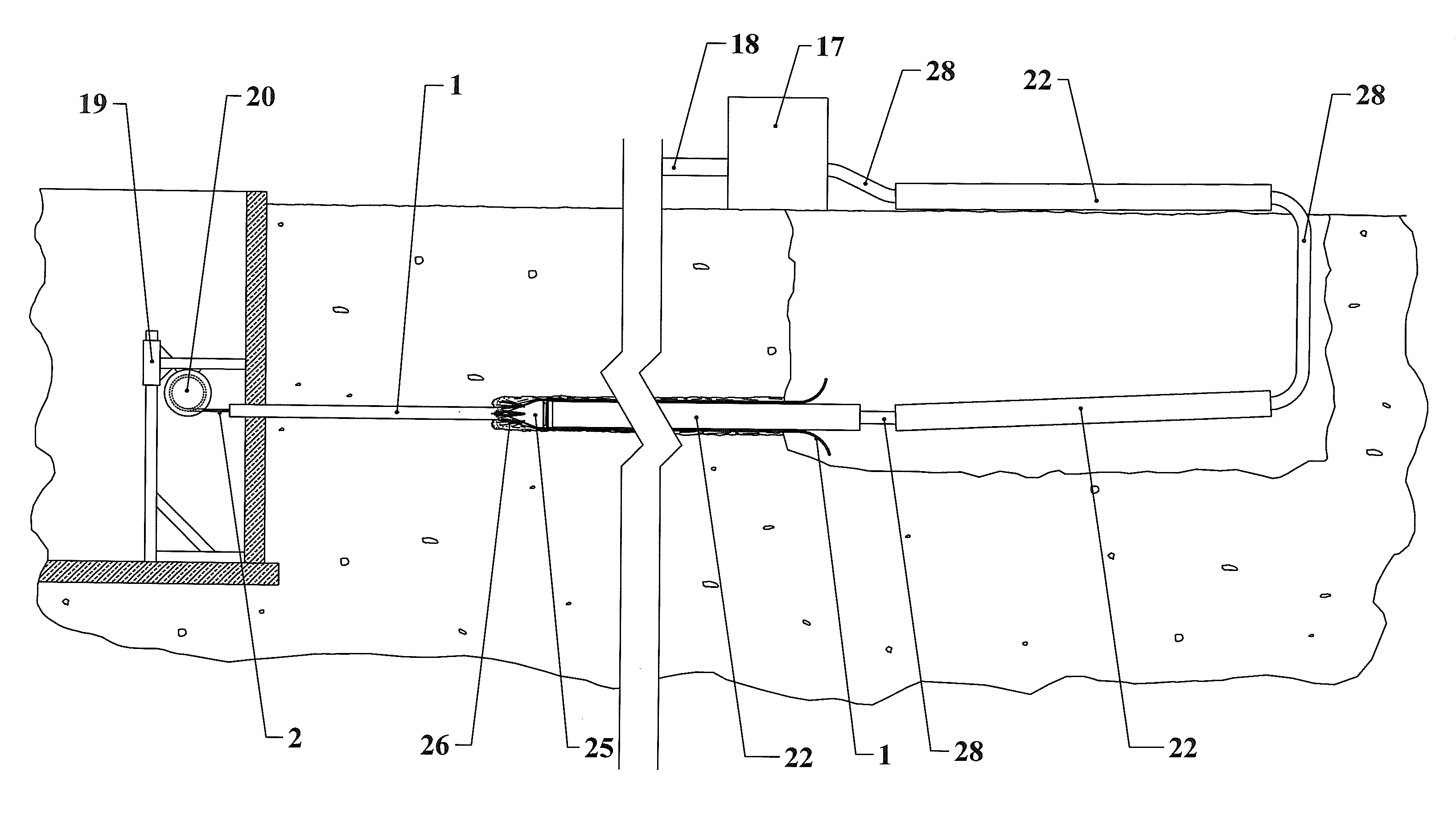
[0027]FIG. 2 of this embodiment is a general overview of the system where the mole along with the replacement pipe are pulled through the prior existing pipe from the upstream end of the pipe to be replaced toward the downstream end of the pipe to be replaced. On the upstream end of the pipe to be replaced are the water source 18, the high pressure water pump 17 and one end of the replacement pipe 15. The opposite end of the replacement pipe 15 is attached to the mole 21 at the hose barb section 14 which is on the upstream end of the mole. On the downstream end of the pipe to be replaced is the pulling devise 20 along with one end of the cable 2. The opposite end of the cable 2 is attached to the mole 21 at the nose section 4 wh...


PUM


Abstract

An apparatus for replacing underground plastic pipe consisting of a mole, flexible cable, pulling devise and water pump. The mole is a cone shaped tool consisting of a nose section, cutting blades, water nozzles and a hose barb. The flexible cable is inserted through the existing pipe, one end is attached to the pulling devise and the other end is attached to the nose section of the mole. Replacement pipe is attached to the hose barb section of the mole on one end and to the water pump on the other end.
As the pulling devise pulls the mole along the path of the existing pipe, the cutting blades split the existing pipe and water from the nozzles erode and moisten the soil surrounding it. The cone shape of the mole expands the split pipe out into the moistened soil, creating clearance for the new pipe being pulled into place.

Description

CROSS REFERENCE TO RELATED APPLICATIONS[0001]U.S. Pat. No. 5,544,977 (Cravy, McCall)[0002]U.S. Pat. No. 6,499,912 B2 (Coon)[0003]US Patent Application Publication No. 2003 / 0223823 A1 (Robinson)BACKGROUND OF INVENTION[0004]Plastic pipe has been in use for underground utility applications for many years. In newer homes and businesses plastic pipe has commonly been used for such applications. These pipes may be made for example, from various types of polymers such as polypropylene (PP), high density polyethylene (HDPE), polyvinyl chloride (PVC) or polybutylene (PB). For various reasons these pipes fail, degrade, rupture or are damaged in some manner and need to be replaced. Polymeric pipes made of polybutylene for example are known to fail and need replacement after prolonged contact with chlorinated water. PB pipe was commonly used for water service from 1978 through 1995. Many homes and businesses currently have PB pipe water service lines and need to have this piping replaced. Anoth...

Claims


Application Information

Patent Timeline
IPC IPC(8): F16L55/18
CPCF16L55/1658
Inventor SUTTON, GERALD STEVEN
Owner MR GERALD STEVEN SUTTON
Why Eureka
Try Eureka