
Arrangement for and method of examining gemstones

a technology of arrangement and method, applied in the direction of lighting support devices, instruments, lighting and heating apparatus, etc., can solve the problems of difficult subjective evaluation and measurement, unsatisfactory use, and low optical efficiency

Inactive Publication Date: 2011-08-25
PHOTOSCRIBE
View PDF41 Cites 15 Cited by
  • Summary
  • Abstract
  • Description
  • Claims
  • Application Information

AI Technical Summary

Benefits of technology

[0008]One aspect of this invention is directed to an arrangement for accurately examining, with repeatability, one or more optical properties such as coverage and / or symmetry of a gemstone, especially a cut, multi-faceted diamond having a table (i.e., the uppermost, largest facet at the top of the diamond) and a culet (i.e., the pointed or blunted bottom of the diamond). An energizable, stationary light source is spaced away from the gemstone and is operative for directing light rays at different orientations to the table of the gemstone when energized.
[0019]Thus, the arrangement of this invention has no rotating light reflectors or moving light sources, as in the prior art, that could cause mechanical variability and vibrations to interfere with the measurements, and thereby degrade measurement accuracy and repeatability. The light emitting diodes of this invention are stationary and are relatively cool-running devices that do not generate heat, as in the prior art, to interfere with the measurements. Rather than moving the light incident on the gemstone, the spaced-apart light sources in one embodiment are energized, one at a time, or the light reflectors in another embodiment simultaneously reflect light incident thereon, thereby obtaining multiple frontlit images to be processed. The arrangement of this invention does not place the gemstone table-side face-down on a glass plate and thus avoids light interference effects, as in the prior art, due to light refraction from a covered table. The arrangement of this invention holds the gemstone in a predetermined, upright position in which the table is uncovered and directly exposed to the light rays. The lack of a glass plate means that no contamination can occur due to dust, dirt, oil from an operator's fingers, scratches, or like contaminants. The arrangement of this invention provides an objective, accurate and repeatable examination of the coverage and symmetry properties of a gemstone essential for true price valuation of the gemstone.

Problems solved by technology

Optical performance of the gemstone, that is, how the gemstone “plays with light”, as well as optical efficiency, that is, how the gemstone “reflects light”, are difficult to subjectively evaluate and measure, even for the experienced human appraiser.
However, as advantageous as such computer-based systems have been, they have not proven to be altogether satisfactory in use.
A moving system component, such as a rotating reflector or a moving light source, causes mechanical variability and vibrations that can interfere with the measurements, and degrade measurement accuracy and repeatability.
The light source also concomitantly generates heat that can interfere with the measurements.
Also, the glass plate on which the gemstone is placed creates an interface at which light interference can occur due to light refraction, thereby again degrading measurement accuracy and repeatability.
This interference effect is aggravated by frequent contamination with dust, dirt, oil from an operator's fingers, scratches, or like contaminants on the glass plate.
Furthermore, the placement of the gemstone on the glass plate is variable, thereby still further worsening measurement accuracy and repeatability.

Method used


Image

  • Arrangement for and method of examining gemstones
  • Arrangement for and method of examining gemstones
  • Arrangement for and method of examining gemstones

Examples


Embodiment Construction

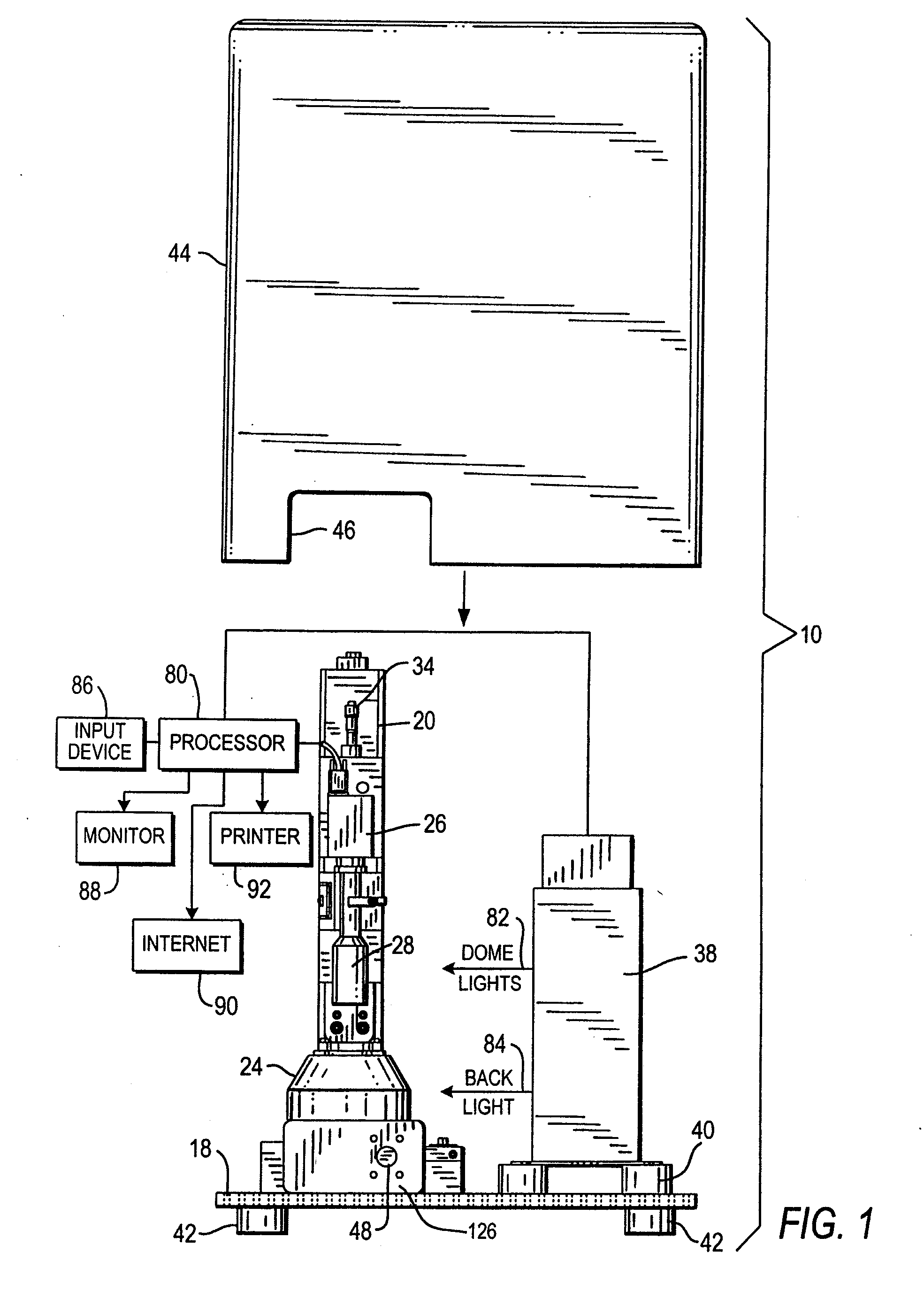
[0035]Referring now to FIG. 1 of the drawings, reference numeral 10 generally identifies an arrangement for accurately determining, with repeatability, one or more optical properties such as coverage and / or symmetry of a gemstone 12, especially a cut, multi-faceted diamond having, as best shown in FIG. 3, a table 14 (i.e., the uppermost, largest facet at the top of the diamond) and a culet 16 (i.e., the pointed or blunted bottom of the diamond). Although FIG. 3 depicts that the gemstone 12 has a round cut, the arrangement 10 is equally applicable for determining the coverage and / or symmetry of gemstones having other cuts, such as oval, pear, marquise, radiant, princess, heart, emerald, etc.

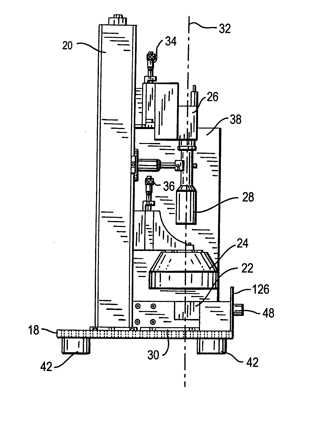
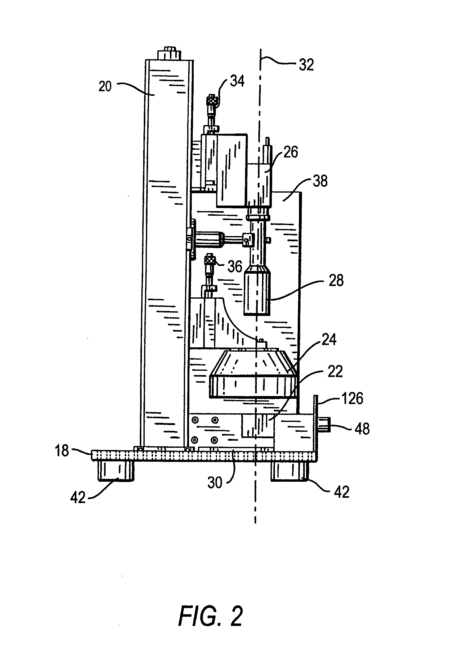
[0036]As shown in FIGS. 1-2, the arrangement 10 includes a horizontal support plate 18, preferably of rigid material, on which an upright, vertical standard 20 is mounted. A gemstone holder 22 or fixture, as best shown in FIGS. 4-11, is mounted on the support plate 18 behind a drawer front panel 1...


PUM

PropertyMeasurementUnit
optical propertyaaaaaaaaaa
diameteraaaaaaaaaa
distancesaaaaaaaaaa

Abstract

An arrangement for, and a method of, accurately determining at least one optical property, such as coverage and / or symmetry, of a gemstone, employ an energizable, stationary light source for directing light rays at different orientations to an uncovered table of the gemstone, and an energizable, stationary backlight spaced away from a culet of the gemstone. A controller energizes the light source to generate return light from the gemstone for each light ray, and energizes the backlight to illuminate the gemstone from behind. An imager images the return light as a plurality of frontlit images, and images the backlit gemstone as a backlit image. The controller processes at least one of the images to determine the optical property of the gemstone.

Description

CROSS REFERENCE TO RELATED APPLICATION[0001]This application claims the benefit of U.S. Provisional Patent Application Serial No. 61 / 308,062, filed Feb. 25, 2010.BACKGROUND OF THE INVENTION[0002]The present invention generally relates to an arrangement for, and a method of, examining gemstones, especially cut diamonds, by illuminating the gemstone, capturing images of the illuminated gemstone, and analyzing the captured images with repeatability.[0003]The beauty and price of a gemstone, such as a cut multi-faceted diamond, are based, for example, on its cut, carat weight, clarity and color. Many different geometrical patterns of cuts, such as round brilliant, oval, pear, marquise, radiant, princess, heart, emerald, etc. are now standardized. The cut, the carat weight, the clarity and the color of the gemstone are typically evaluated and / or measured by a human appraiser. Such evaluated and / or measured properties are often objectively presented to a consumer, typically in certificate ...

Claims


Application Information

Patent Timeline
Patent Type & Authority Applications(United States)
IPC IPC(8): G06K9/00G01N21/00F21S4/00F21V7/00
CPCG01N21/87G01N21/8806
Inventor BENDERLY, DAVIDVANANDEN, JASON IANLIATTI, DAVID
Owner PHOTOSCRIBE
Learn More