On-vehicle image processing device

a technology for processing devices and vehicles, applied in the field of on-vehicle image processing devices, can solve problems such as increasing image processing load, and achieve the effect of accurate correction of telephoto image processing

Inactive Publication Date: 2010-07-08
TOYOTA JIDOSHA KK
View PDF7 Cites 24 Cited by
  • Summary
  • Abstract
  • Description
  • Claims
  • Application Information

AI Technical Summary

Benefits of technology

[0004]Accordingly, the invention has been made in order to solve the above-mentioned problems, and an object of the invention is to provide an image processing device that effectively performs image processing for calculating the amount of movement of a vehicle while maintaining the calculation accuracy of the amount of movement.
[0006]According to the above-mentioned structure, the image processing device can process only a predetermined specific region in the image region composed of the captured image information. Therefore, it is possible to effectively perform image processing. In addition, since the image processing device extracts, from the image region, a plurality of specific regions each of which is closer to the edge of the image region, in which the displacement of the captured object is large, than to the center of the image region, it is possible to accurately check the displacement of an image in the vertical direction and the horizontal direction and thus calculate the amount of movement of the vehicle. Therefore, it is possible to effectively calculate the amount of movement of the vehicle while ensuring the accuracy.
[0008]According to the above-mentioned structure, in the case of left-hand traffic, the image processing device can extract the upper left region and the lower right region of the entire region of the image information with respect to the center as the specific regions. Therefore, it is possible to accurately place objects serving as feature points, such as a building or a traffic sign disposed on the upper left side of the traveling direction, and a white line or a center divider disposed on the lower right side of the traveling direction, into the specific regions.
[0010]According to the above-mentioned structure, it is possible to acquire a plurality of images using the imaging units with different angles of view. In this case, the amount of image information of the image captured by the first imaging unit (wide-angle imaging unit), which has an angle of view more than that of the second imaging unit, is more than that of the image captured by the second imaging unit (narrow-angle imaging unit) in the imaging direction. Therefore, it is possible to more accurately check the displacement of an image by using the image captured by the wide-angle imaging unit to detect the displacement of an object. As such, when a plurality of imaging units with different angles of view is provided, the image captured by the imaging unit with a large angle of view is used to calculate the amount of movement of the vehicle, and the image captured by the other imaging unit is corrected on the basis of the calculated amount of movement of the vehicle. Therefore, it is possible to accurately correct an image.
[0012]According to the above-mentioned structure, it is possible to extract the central region of the image information and acquire two images, that is, the entire image and the image of the central region. In this way, it is possible to correct the image of the central region on the basis of the amount of movement calculated from a specific region that is closer to the edge of the image region. The image of the central region corresponds to an image captured by a telephoto imaging unit (narrow-angle imaging unit) and the image of a specific region close to the edge corresponds to an image captured by a wide-angle imaging unit. Therefore, it is possible to accurately correct telephoto image processing using one image, without using two imaging units.

Problems solved by technology

However, in the image processing device according to the related art, when an object on the screen is moved a long distance, it is necessary to process a relatively large image region in order to follow the object, which may result in an increase in the load of image processing.

Method used


Image

  • On-vehicle image processing device
  • On-vehicle image processing device
  • On-vehicle image processing device

Examples


first embodiment

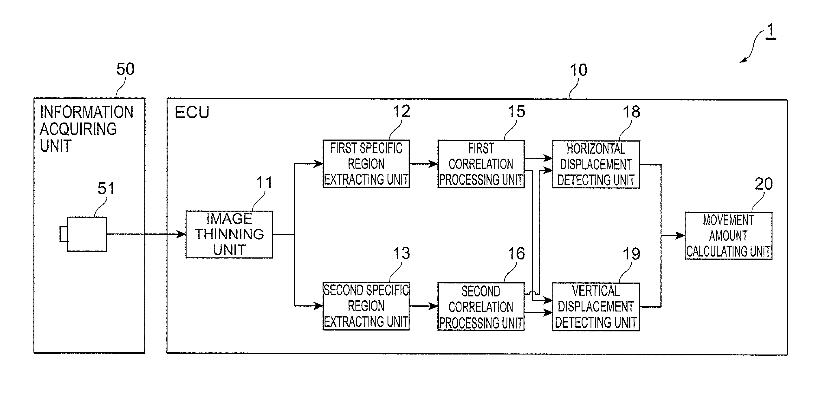
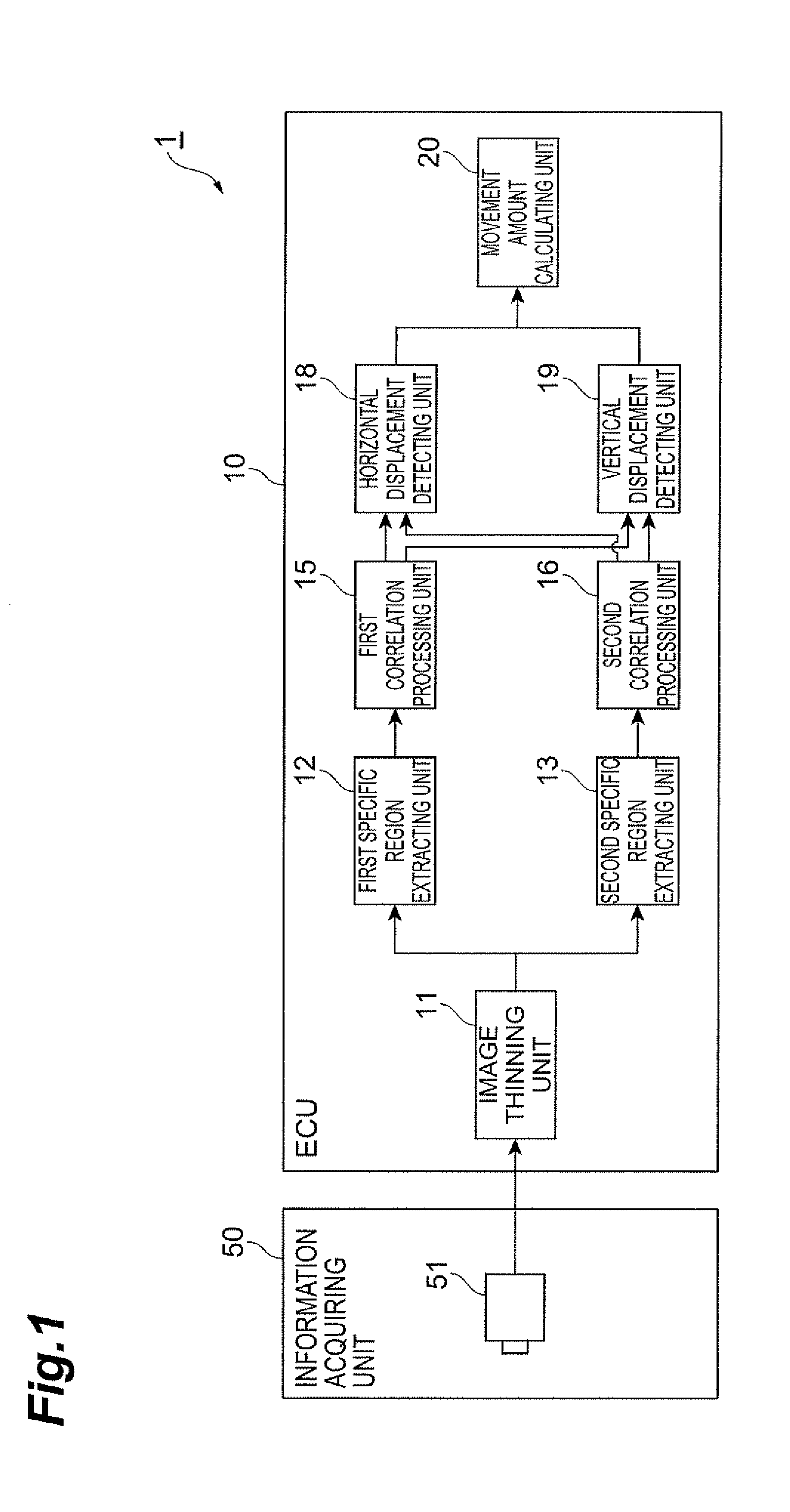
[0023]FIG. 1 is a diagram schematically illustrating the structure of an on-vehicle image processing device 1 according to a first embodiment of the invention. The on-vehicle image processing device 1 according to this embodiment is applicable to, for example, a drive assist system that acquires the amount of movement of a vehicle from image information and controls the driving of the vehicle.

[0024]As shown in FIG. 1, the on-vehicle image device 1 according to this embodiment includes an information acquiring unit 50 and an ECU 10. The ECU (electronic control unit) is a computer that electronically controls vehicle devices, and includes, for example, a CPU (central processing unit), a ROM (read only memory), a RAM (random access memory), and an input / output interface.

[0025]The information acquiring unit 50 includes a first camera (first imaging unit) 51. The first camera 51 includes an image sensor that acquires the image information of the periphery of a vehicle. For example, a CCD...

second embodiment

[0041]Next, an image processing device according to a second embodiment of the invention will be described.

[0042]An image processing device 2 according to the second embodiment has substantially the same structure as the image processing device 1 according to the first embodiment shown in FIG. 1 except that it includes a third specific region extracting unit 14 and a third correlation processing unit 17. Therefore, in the second embodiment, the same components as those in the first embodiment are denoted by the same reference numerals as those in the first embodiment, and a description thereof will be omitted. The third specific region extracting unit 14 and the third correlation processing unit 17 will be described in detail below.

[0043]FIG. 4 is a diagram schematically illustrating the structure of the image processing device 2 according to this embodiment. The image processing device 2 according to this embodiment includes an information acquiring unit 50 and an ECU 10. The ECU 1...

third embodiment

[0050]Next, an image processing device according to a third embodiment of the invention will be described.

[0051]An image processing device 3 according to the third embodiment has substantially the same structure as the image processing device 1 according to the first embodiment shown in FIG. 1 except that it includes a second camera (second imaging unit) 52 and an image correcting unit (first correcting unit) 22. Therefore, in the third embodiment, the same components as those in the first embodiment are denoted by the same reference numerals as those in the first embodiment and a detailed description thereof will be omitted. The second camera 52 and the image correcting unit 22 will be described in detail below.

[0052]FIG. 5 is a diagram schematically illustrating the structure of the image processing device 3 according to this embodiment, FIG. 6 is a diagram illustrating an example of the arrangement of an information acquiring unit 50 of the image processing device 3 according to ...


PUM


Abstract

An image processing device includes a first camera that captures the periphery of a vehicle, specific region extracting units that extract regions, each of which is closer to the edge of an image than to the center of the image, as specific regions, and a movement amount calculating unit that calculates the amount of movement of the vehicle on the basis of image information in a plurality of specific regions. Therefore, it is possible to process only the first specific region and the second specific region of the captured image and thus effectively perform image processing.

Description

TECHNICAL FIELD[0001]The present invention relates to an on-vehicle image processing device.BACKGROUND ART[0002]A device has been proposed which uses image information captured by, for example, an on-vehicle camera in order to control the driving of a vehicle (for example, see JP-A-7-89443). The device limits an image processing range and controls the vehicle such that there is an object in the limited range.DISCLOSURE OF THE INVENTION[0003]However, in the image processing device according to the related art, when an object on the screen is moved a long distance, it is necessary to process a relatively large image region in order to follow the object, which may result in an increase in the load of image processing. Similarly, when the image processing device has a function of detecting the amount of movement of the vehicle from the displacement of the object, it is also necessary to process a relatively large image region.[0004]Accordingly, the invention has been made in order to so...

Claims


Application Information

Patent Timeline
Patent Type & Authority Applications(United States)
IPC IPC(8): G06K9/00
CPCG06T7/204G06T2207/30252G06T2207/10016G06T7/248
Inventor AKUTSU, EISAKU
Owner TOYOTA JIDOSHA KK
Why Eureka
Try Eureka