Intracorporeal marker and marker delivery device

a technology of intracorporeal markers and delivery devices, which is applied in the field of intracorporeal markers and marker delivery devices, can solve the problems of misdirected follow-up treatments to an undesired portion of the patient's tissue, inability to heal or otherwise change, and inability to accurately detect the patient, etc., to achieve the effect of enhancing expansion, facilitating detection, and enhancing expansion

Inactive Publication Date: 2011-07-28
SENORX
View PDF99 Cites 50 Cited by
  • Summary
  • Abstract
  • Description
  • Claims
  • Application Information

AI Technical Summary

Benefits of technology

[0022]The fibrous marker should be slidably disposed within the inner lumen of the delivery cannula, preferably proximal to at least one short term marker so that upon discharge from the cannula into a target site, the fibrous marker will block the accessing passageway and prevent loss of marker material therethrough. A suitable material for forming the fibrous marker is a felt and / or fiber material formed of oxidized regenerated cellulose which has an in vivo lifetime of a few hours up to about 6 weeks, typically about 3 days to about 4 weeks. However, the fibrous marker may be formed of a bioabsorbable polymer such as polylactic acid or polyglycolic acid, a co-polymer of polylactic acid and polyglycolic acid, polycaprolactone, collagen and mixtures thereof, including mixtures with oxidized regenerated cellulose. Suitable oxidized, regenerated cellulose includes SURGICEL™ from the Ethicon Division of Johnson & Johnson or other suitable oxidized regenerated cellulose which are naturally hemostatic. Alternatively, a hemostatic agent such as collagen, gelatin or polysaccharides may be incorporated into the fibrous material to provide the hemostasis upon contact with blood. A wide variety of other hemostatic agents may be incorporated into the marker. The thrombus formed by the hemostasis is formed very quickly to fill the cavity at the biopsy site and at least temporarily hold the plug and any other markers in position within the cavity. Anesthetic agents to control post procedure pain, chemotherapeutic agents to kill any residual neoplastic tissue and coloring agents (e.g. carbon black and methylene blue) for visual location of the biopsy site, may also be incorporated into the fibrous marker.
[0029]The ultrasound-detectable biopsy site markers of the present invention provide several advantages. A biopsy cavity with marker material having features of the present invention provides a large USI-bright mass, making it much easier, for example, to distinguish the ultrasound signal of the marker from signals arising naturally from within a breast. The marker materials produce bright ultrasound echo signals from one portion of the filled region, which contrasts with the dark ultrasound shadow region immediately behind the bright ultrasound echo region. The strength of the reflected signal, and the contrast with the shadow region, make the marked site readily detectable. Such ready detectability allows, for example, less-experienced physicians to perform the identification by USI and the subsequent surgical resection without the need for an interventional radiologist to identify and mark the biopsy cavity. When a MRI marker element is incorporated into the releasable plug or the short term markers, the target site in which the markers are deployed may be subsequently detected by ultrasound, magnetic resonance and X-ray without interfering with imaging adjacent tissue at a later date.
[0030]One advantage of the embodiment of the invention directed to the elongated intracorporeal remotely detectable marker having a core and outer jacket is that by having a two layer core / jacket marker body, upon contact with a body fluid or other water based fluid, the length of the fibrous marker remains about the same but the wrapped structure unfolds upon swelling. This “unfolding” creates more surface area subject to exposure to the fluid to enhance expansion, and potentially provides a larger imaging characteristic than would be possible with an unwrapped single layer marker of similar initial shape, i.e., a core alone.
[0031]The invention provides the advantages of securely retaining markers within a marker delivery device, improving accuracy and avoiding errors in placement of markers at desired locations within a patient's body, preventing ingress of tissue into the distal tip of the device when it is advanced through tissue, and guiding the device by use of an imaging device including ultrasound, X-ray and magnetic resonance based devices.

Problems solved by technology

However, radiographically visible tissue features, originally observed in a mammogram, may be removed, altered or obscured by the biopsy procedure, and may heal or otherwise become altered following the biopsy.
This, in turn, can result in follow-up treatments being misdirected to an undesired portion of the patient's tissue.
Such a marker enables a follow-up procedure to be performed without the need for traditional radiographic mammography imaging which, as discussed above, can be subject to inaccuracies as a result of shifting of the location wire as well as being tedious and uncomfortable for the patient.

Method used


Image

  • Intracorporeal marker and marker delivery device
  • Intracorporeal marker and marker delivery device
  • Intracorporeal marker and marker delivery device

Examples


Embodiment Construction

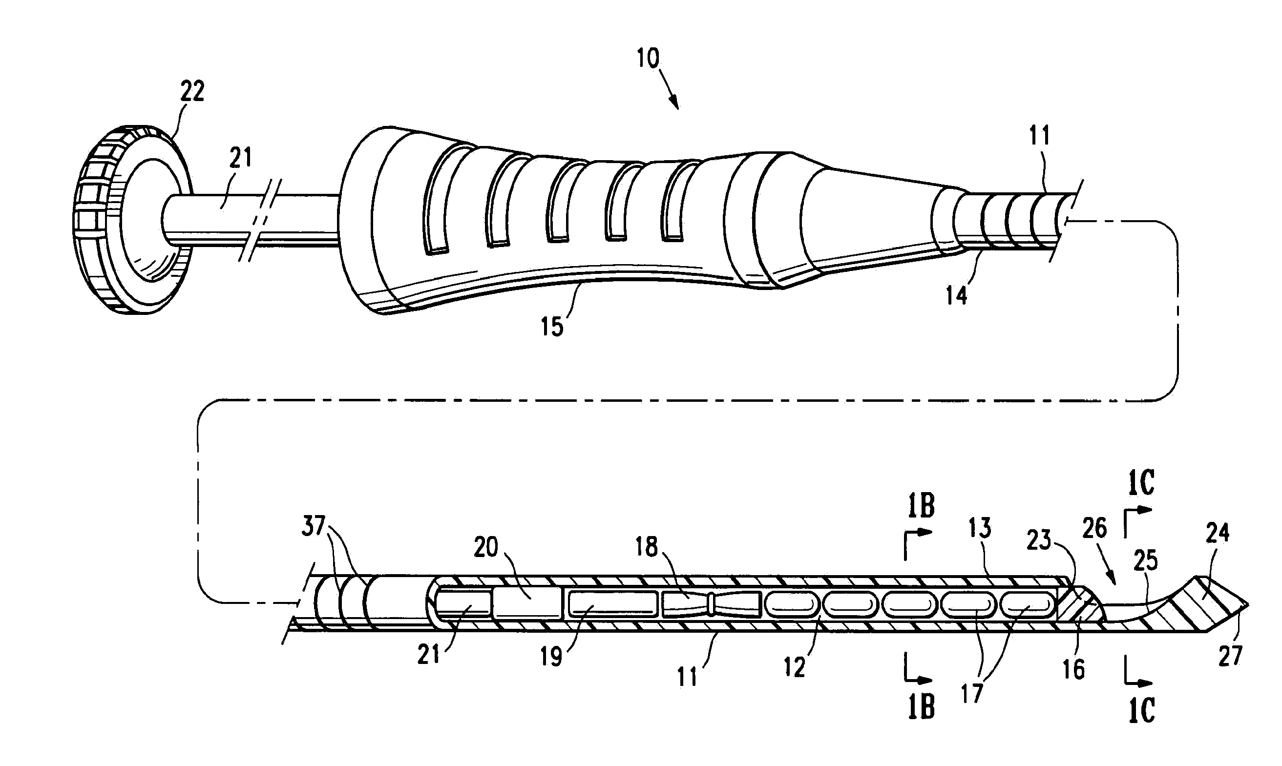
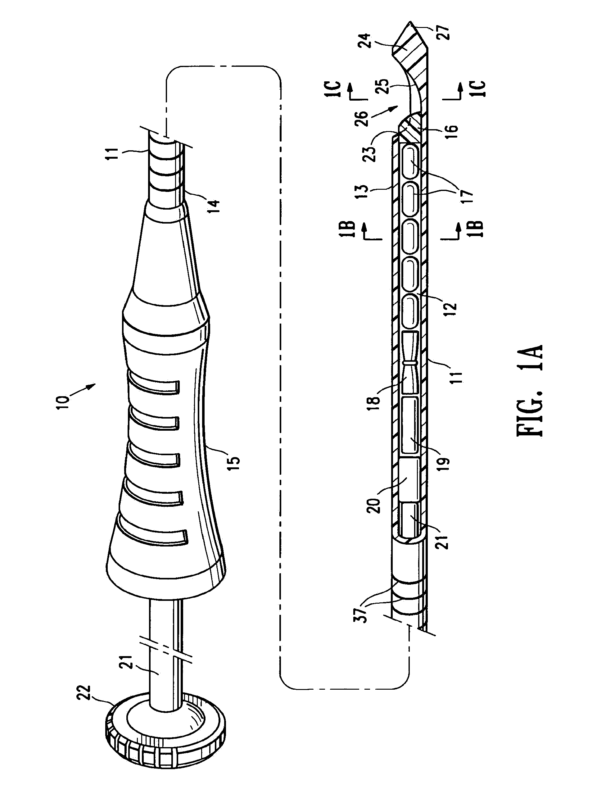
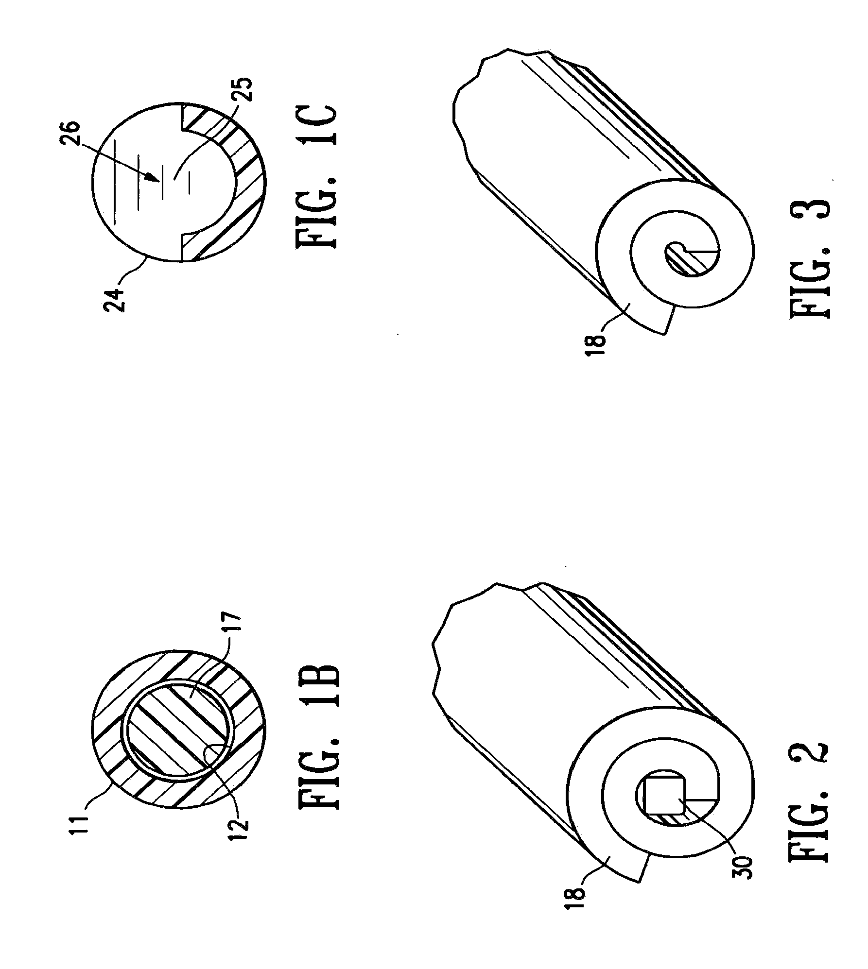
[0043]FIGS. 1A-1C illustrate a marker delivery device 10 embodying features of the invention which includes a delivery tube or cannula 11 with a bore 12, a distal portion 13, and a proximal portion 14 with a handle 15. A releasable distal plug 16, several (five) short term markers 17, a pair of fibrous markers 18 and 19 and a proximal plug 20 are shown disposed within the bore 12. A plunger 21 is slidably disposed within the tube bore 12, and is provided with a proximal end 22 configured to allow an operator to press the plunger further into the bore 12 and push the releasable plug 16 and one or more of the other markers out of the discharge port or opening 23 in the distal end 24 of delivery tube 11. Cannula handle 15 allows an operator to hold the cannula steady while pressing plunger 21 to discharge the releasable plug 16 and markers 17 and 18.

[0044]Releasable plug 16 may substantially fill the discharge opening 23, as shown in FIG. 1, or may occupy or block only a portion of the...


PUM


Abstract

An elongated intracorporeal remotely detectable marker includes a core of bioabsorbable fibers. An outer jacket of bioabsorbable fibers is disposed around at least part of the core. In one embodiment, for example, the core has a longitudinal extent and a pair of opposed ends, and the outer jacket is disposed around the longitudinal extent of the core, with the pair of opposed ends being exposed.

Description

RELATED APPLICATIONS[0001]This application is a continuation-in-part of application Ser. No. 12 / 214,398 entitled MARKER DELIVERY DEVICE WITH RELEASABLE PLUG, filed Jun. 18, 2008, which is a divisional of application Ser. No. 10 / 753,694, filed Jan. 7, 2004, which is a continuation-in-part of application Ser. No. 10 / 444,770, filed May 23, 2003.[0002]Also, this application is a continuation-in-part of U.S. patent application Ser. No. 12 / 852,286 entitled CAVITY-FILLING BIOPSY SITE MARKERS, filed Aug. 6, 2010, which is a continuation of U.S. patent application Ser. No. 10 / 990,327, filed Nov. 16, 2004, now U.S. Pat. No. 7,792,569, which is a continuation of U.S. patent application Ser. No. 10 / 124,757, filed Apr. 16, 2002, now U.S. Pat. No. 6,862,470, which is a continuation-in-part of U.S. patent application Ser. No. 09 / 717,909, filed Nov. 20, 2000, now U.S. Pat. No. 6,725,083, which is a continuation-in-part of U.S. patent application Ser. No. 09 / 343,975, filed Jun. 30, 1999, now U.S. Pa...

Claims


Application Information

Patent Timeline
Patent Type & Authority Applications(United States)
IPC IPC(8): A61B6/00
CPCA61B17/0057A61B19/54A61B2017/00637A61B2019/5487A61B2019/5408A61B2019/5425A61B2017/00898A61B90/39A61B2090/3908A61B2090/3925A61B2090/3987
Inventor JONES, MICHAEL L.LUBOCK, PAULMERRITT, JOHN
Owner SENORX
Why Eureka
Try Eureka