
Microsampling apparatus and sampling method thereof

a microsampling and sampling method technology, applied in material analysis using wave/particle radiation, instruments, nuclear engineering, etc., can solve problems such as quantitative and qualitative deteriorations, degradation of the quality of an observation image, and more noticeable problems

Inactive Publication Date: 2011-07-28
HITACHI LTD
View PDF6 Cites 4 Cited by
  • Summary
  • Abstract
  • Description
  • Claims
  • Application Information

AI Technical Summary

Benefits of technology

[0014]Use of the method (b) results in an unwanted change in composition of the specimen of interest. This causes undesired mixture of an extra signal as derived from the conductive thin-film during analysis after the sampling, thereby complicating the analyzation of a result.
[0016]It is therefore a first object of the present invention to achieve, in a sampling apparatus having an observation system of the type using charged particles, reduction of electrification of an electrically insulative specimen at any given positions on the specimen, thereby to assure observation performance.
[0021]According to this invention, it is possible to achieve the sampling of an insulator specimen on an insulative substrate even in the state that an electron beam is irradiated thereonto.

Problems solved by technology

The electrification can sometimes cause degradation of the quality of an observation image and also the occurrence of quantitative and qualitative deteriorations of signals of secondary electrons and reflected electrons or the like along with undesired scattering of a constituent material(s) of the insulator specimen.
These problems become more noticeable as the insulator specimen becomes higher in electrical resistivity.

Method used


Image

  • Microsampling apparatus and sampling method thereof
  • Microsampling apparatus and sampling method thereof
  • Microsampling apparatus and sampling method thereof

Examples


embodiment 1

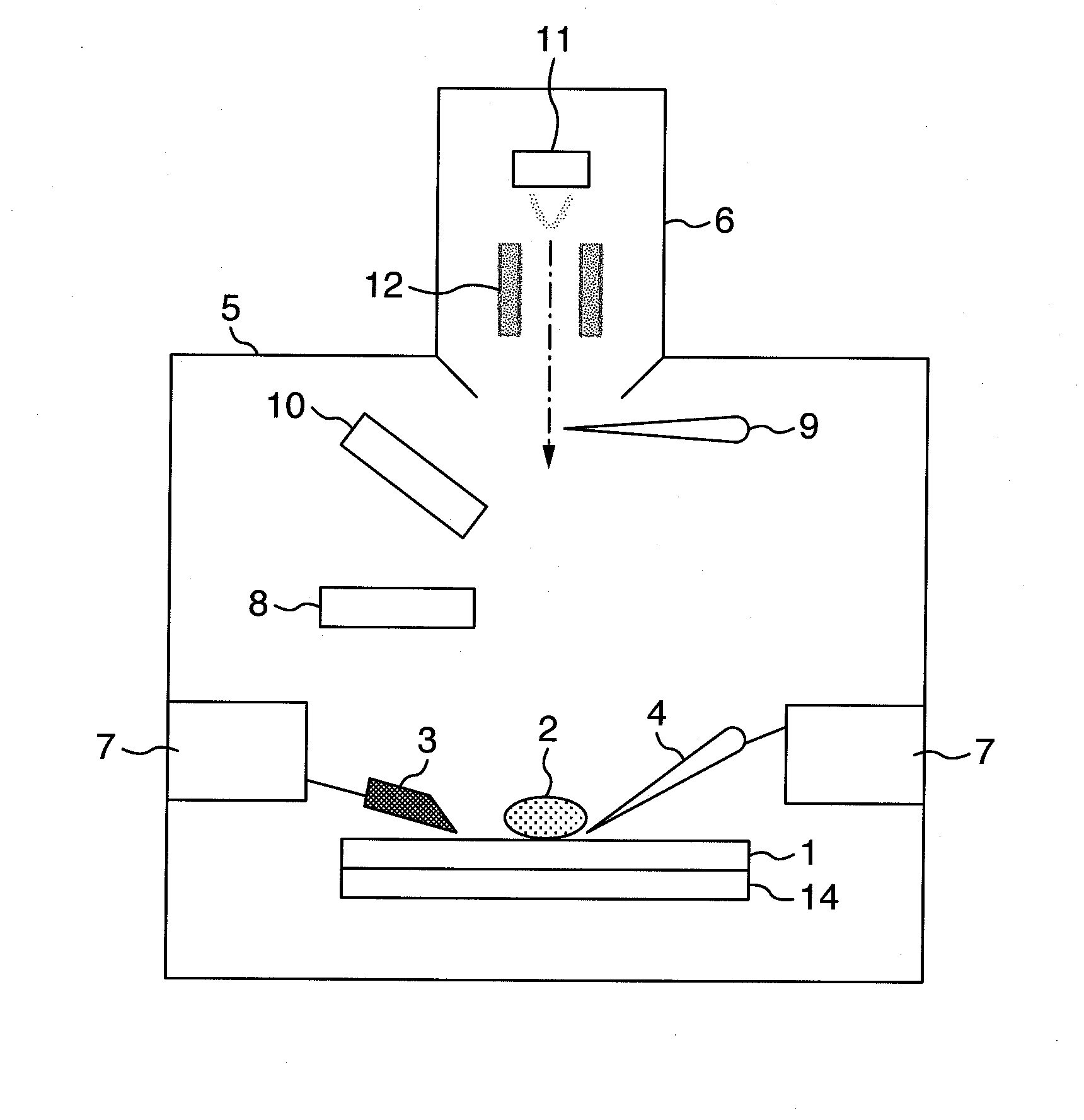
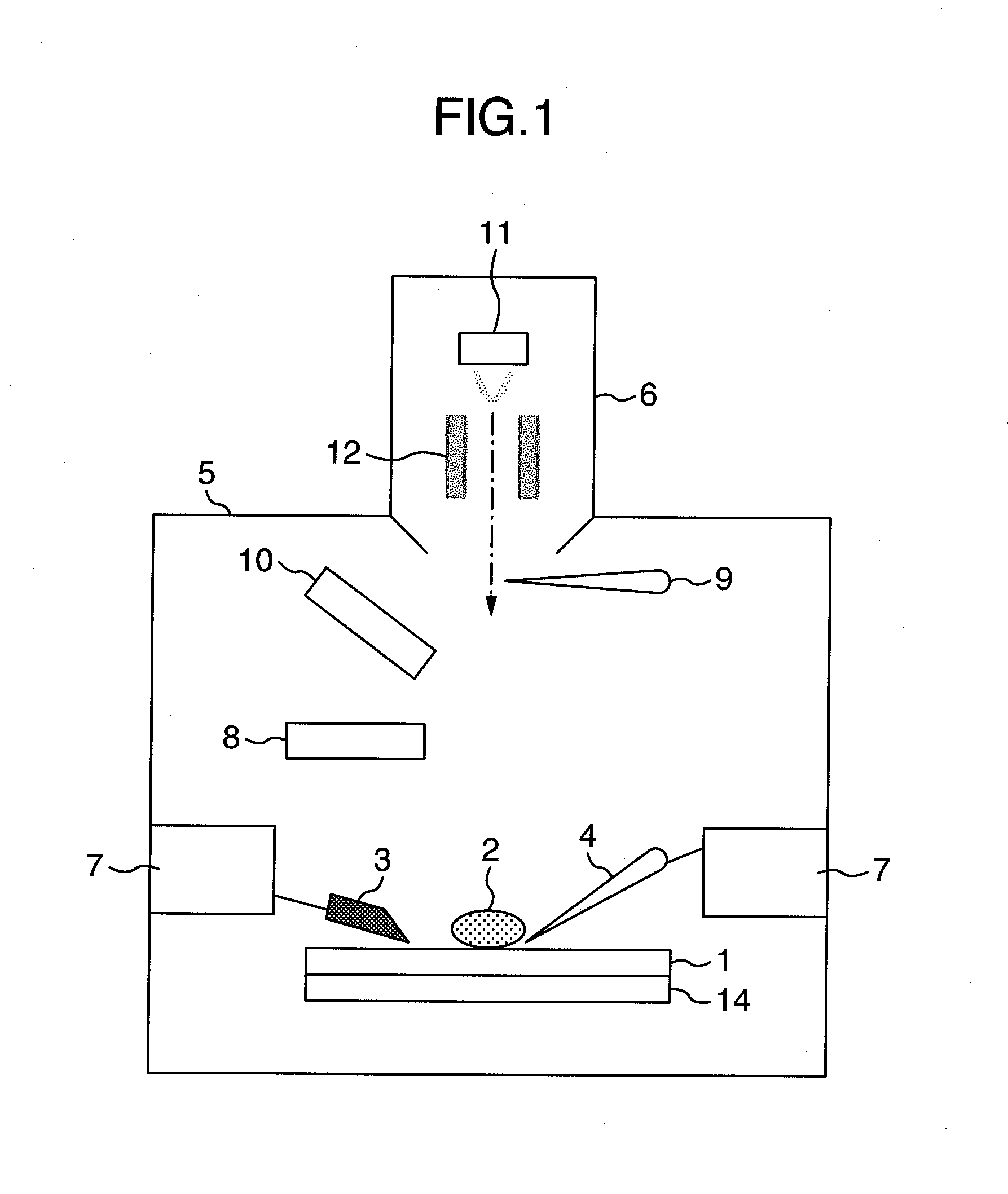
[0030]One important feature of a microsampling apparatus in accordance with this embodiment is that the apparatus has a terminal for electrification suppression and specimen sampling to thereby enable execution of the sampling of an electrically insulative specimen while at the same time performing electron microscope (EM) observation. More specifically, the microsampling apparatus performs observation and cutting processes while suppressing the electrification and performs electrostatic sampling of an insulative micro-specimen which is slightly electrified.

[0031]FIG. 1 is a diagram showing, in schematic cross-section, a configuration of the first embodiment of this invention. Reference numeral 1 of FIG. 1 designates an electrically insulative substrate; numeral 2 indicates a small or “micro” insulator specimen on the insulative substrate 1; 3 denotes a cutting tool; 4 is a terminal; 5, a specimen / sample chamber; 6, an electron gun; 7, a manipulator for operating the cutting tool 3 ...

embodiment 2

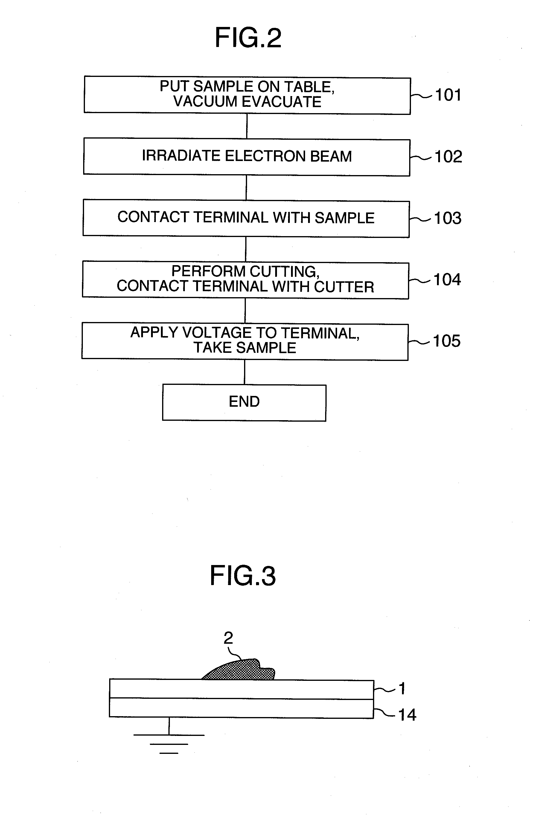
[0037]An explanation will next be given of a method for picking up foreign matter which is negatively electrifiable upon irradiation of an electron beam. The steps 101 to 103 of the above-stated embodiment are the same. At step 104, the diamond-made cutting tool 3 provided at the manipulator 7 is used to cut and isolate a foreign object (specimen 2) from the substrate 1 in a similar way to the embodiment 1. The micro insulator specimen 2 which is mounted on the cutting tool 3 is electrified to have the negative polarity. At step 105, the terminal 4 that was brought into contact with the substrate 1 is driven to move toward the micro insulator specimen 2 on the cutting tool 3; then, a positive voltage is applied to the terminal 4 by the potential control mechanism 13 so that the negatively electrified foreign object 2 is electrostatically picked up at the end of the terminal 4. As the electrification quantity of the foreign object 2 depends upon the material and shape of this foreign...

embodiment 3

[0038]Next, an explanation will be given of an example having as the foreign matter pickup mechanism a tweezers-shaped grasp / holding mechanism consisting essentially of two arms. The micro-specimen grasp / hold mechanism is a tool or instrument for plucking up a very small thing with its size being on the order of submicrometers, which tool is built in the manipulator 7 and operates to pick up a small thing by utilizing the phenomenon that the voltage application to an electrostatic actuator causes the micro specimen grasp / hold mechanism to become narrower in distance between ends thereof.

[0039]In this embodiment, there will be explained (1) a merit of cutting performance in the case of the grasp / hold mechanism being used and (2) a merit of scattering prevention in the case of the grasp / hold mechanism being used. (1) A specimen large in brittleness sometimes breaks or wrecks during cutting, resulting in failure to perform sampling. By surely grasping such brittle specimen by the grasp...


PUM


Abstract

A microsampling apparatus having a mechanism for enabling observation of a specimen and for contacting a potential-controllable conductive terminal with a sampling area and a sampling method thereof are provided. The mechanism includes an operation mechanism for precisely controlling, during the observation, a conductive terminal for contact with a periphery of the sampling area and movement of the terminal, a potential control mechanism for applying a voltage to the terminal, and a mechanism for coupling the terminal to ground and to the potential control mechanism. Contacting the terminal with a vicinity of the specimen allows charged particles that are created during the observation and sampling to escape via an earth lead. This makes it possible, in analysis preprocessing of a small insulator specimen of about 1 μm which causes device defects, to lessen electrification risks, thereby enabling sampling of only the target object without mixture of a surrounding base material.

Description

INCORPORATION BY REFERENCE[0001]The present application claims priority from Japanese application JP 2010-014995 filed on Jan. 27, 2010, the content of which is hereby incorporated by reference into this application.BACKGROUND OF THE INVENTION[0002]The present invention relates to a microsampling apparatus for isolating and sampling a small object on a workpiece substrate, and also relates to a sampling method thereof.[0003]In electronic device manufacturing / fabrication processes, it is required to continue to mass-produce nondefective products. Due to the fact that the number of products is extra-large, the occurrence of a defect leads to a decrease in product yield or to stoppage of a production line(s), which will greatly affect the commercial profit. For this reason, efforts are made to eliminate defective products and promote cause investigation. Practically, the identification of very small foreign matter that causes detection is carried out by a variety of analyses. In such a...

Claims


Application Information

Patent Timeline
IPC IPC(8): G01N23/00
CPCG01N2001/2873G01N23/2202
Inventor IWANAMI, TAKASHIHORIKOSHI, KAZUHIKO
Owner HITACHI LTD
Learn More