
Methods of manufacturing induction rotors with conductor bars having high conductivity and rotors made thereby

a technology of conductor bars and rotors, which is applied in the field of manufacturing induction rotors, can solve the problems of reducing the durability of electric motors, reducing the electric motor's durability, and limiting the use of copper, so as to improve the electric conductivity and durability of rotors, the effect of high conductiv

Active Publication Date: 2011-07-21
GM GLOBAL TECH OPERATIONS LLC
View PDF17 Cites 33 Cited by
  • Summary
  • Abstract
  • Description
  • Claims
  • Application Information

AI Technical Summary

Benefits of technology

The invention is about improving the electric conductivity and durability of rotors for electric machines. It involves using high conductive and durable conductor bars, such as copper bars, with light weight aluminum end rings. The conductor bars are joined with the end rings by positioning them in squirrel slots of a laminate steel stack and bending or welding them to hold the stack together. The conductor bars can be preformed or formed in the squirrel slots. The invention can be applied to AC induction motors and other types of electric machines. The technical effect is to enhance the metallurgical bonding between the conductor bars and the end rings, which improves the electric conductivity and durability of the rotors.

Problems solved by technology

Because of its high density and melting point, however, copper has limitations and / or unique problems in rotor applications, particularly for hybrid systems.
In hybrid applications, a high speed (e.g., more than 10,000 rpm) electric motor is usually needed due to space limitations in automotive vehicles.
High density copper can produce very high centrifugal force and inertia at high rpm, and can significantly reduce the durability of the electric motor.
Premature damage in rotor bearings is often seen in practice.
The high melting point of copper (1083° C.) significantly reduces die life and increases the manufacturing cost of copper rotors.
Although cast aluminum rotors (bars and end rings together) overcome the shortfalls of high rotating inertia and low die life associated with copper material, the low mechanical properties, in particular, the low electric (pure Al: IACS 62%) and thermal conductivity of aluminum alloys, particularly when the cast aluminum conductor bars have casting defects including hot-tear cracks, porosity, and oxide inclusion etc, impose a great challenge for their successful application in electric motors.
In addition, the aluminum alloys used to cast rotor squirrel cages are usually high purity aluminum, high purity aluminum casting alloys, or electric grade wrought alloys which are all difficult to cast because of their low fluidity, high shrinkage rate (density change from liquid to solid), high melting temperature, and large freezing range (temperature difference between liquidus and solidus), etc.
These characteristics of the higher purity aluminum alloys increase porosity and the tendency of hot tearing, particularly at the locations where the conductor bars connect to the end rings, which leads to fracture between the conductor bars and the end rings.
The entrained air and abundant aluminum oxides produced during the high pressure die casting process, which are due to very high flow velocity (about 60 m / s) in mold filling, can not only decrease rotor quality and durability, but also significantly reduce the thermal and electric conductivity of the rotor, particularly in the conductor bars.
Because of the casting defects present in the cast aluminum conductor bars, the bars may be broken during motor operation.
The broken bars will further reduce rotor conductivity and motor performance.

Method used


Image

  • Methods of manufacturing induction rotors with conductor bars having high conductivity and rotors made thereby
  • Methods of manufacturing induction rotors with conductor bars having high conductivity and rotors made thereby
  • Methods of manufacturing induction rotors with conductor bars having high conductivity and rotors made thereby

Examples


Embodiment Construction

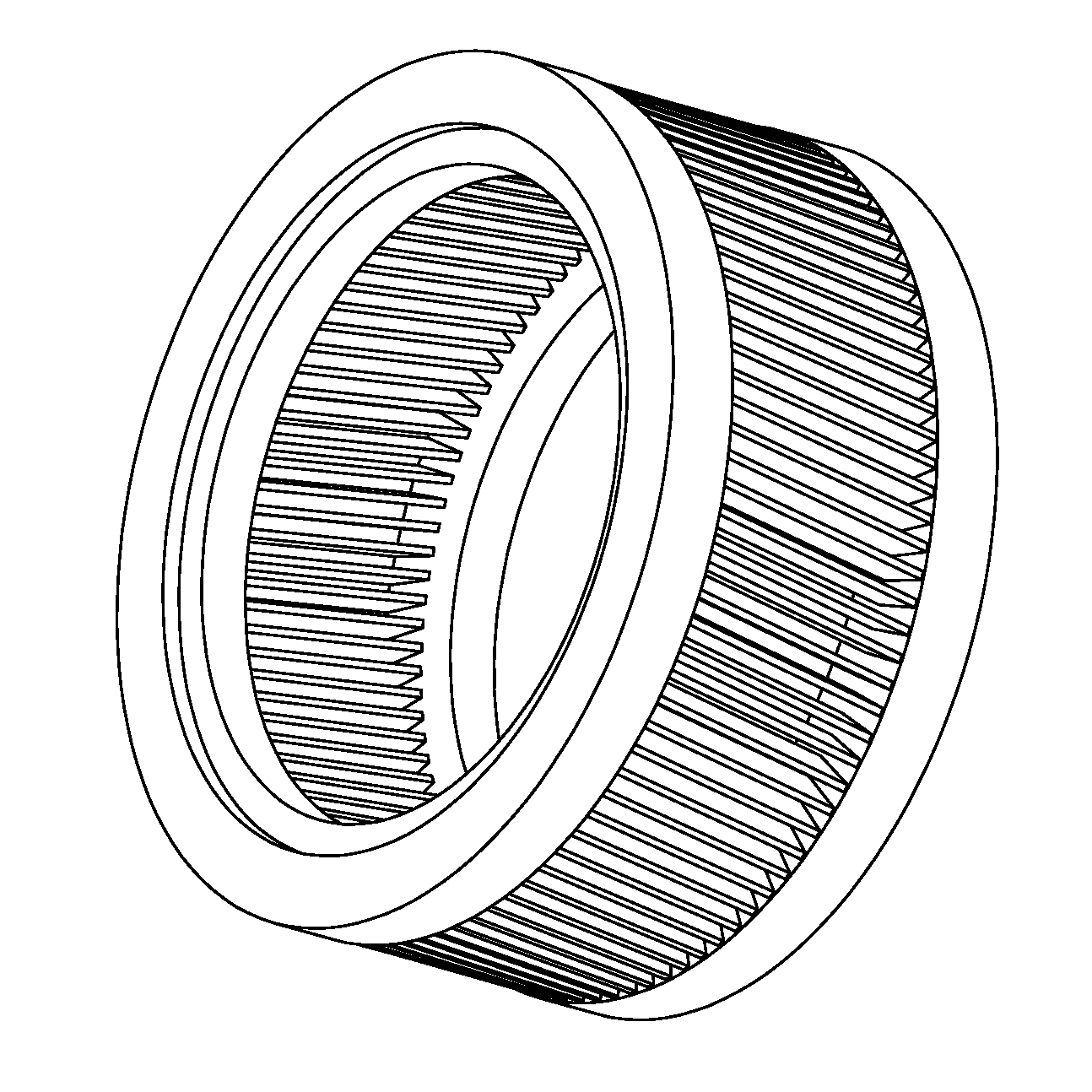
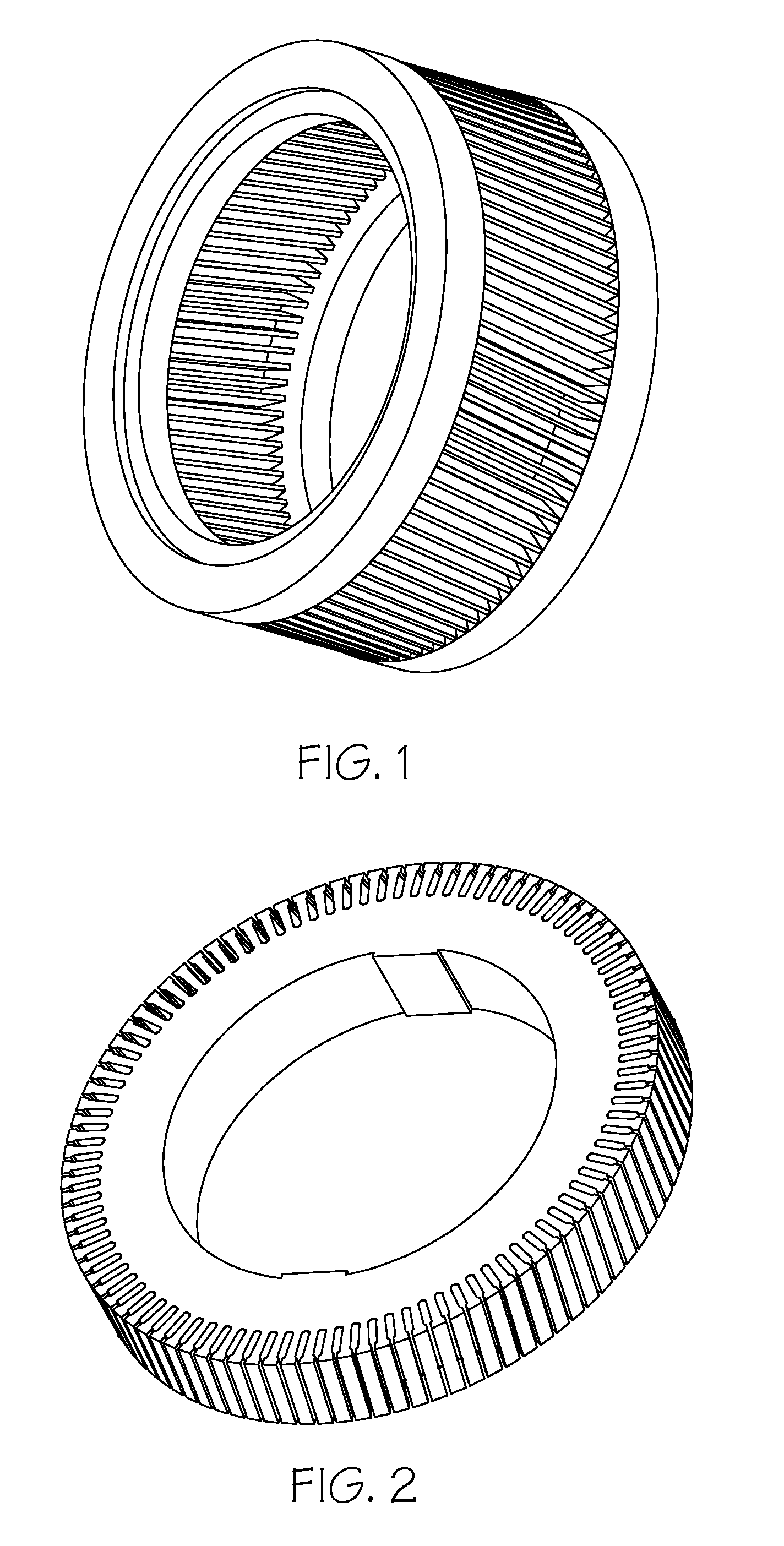
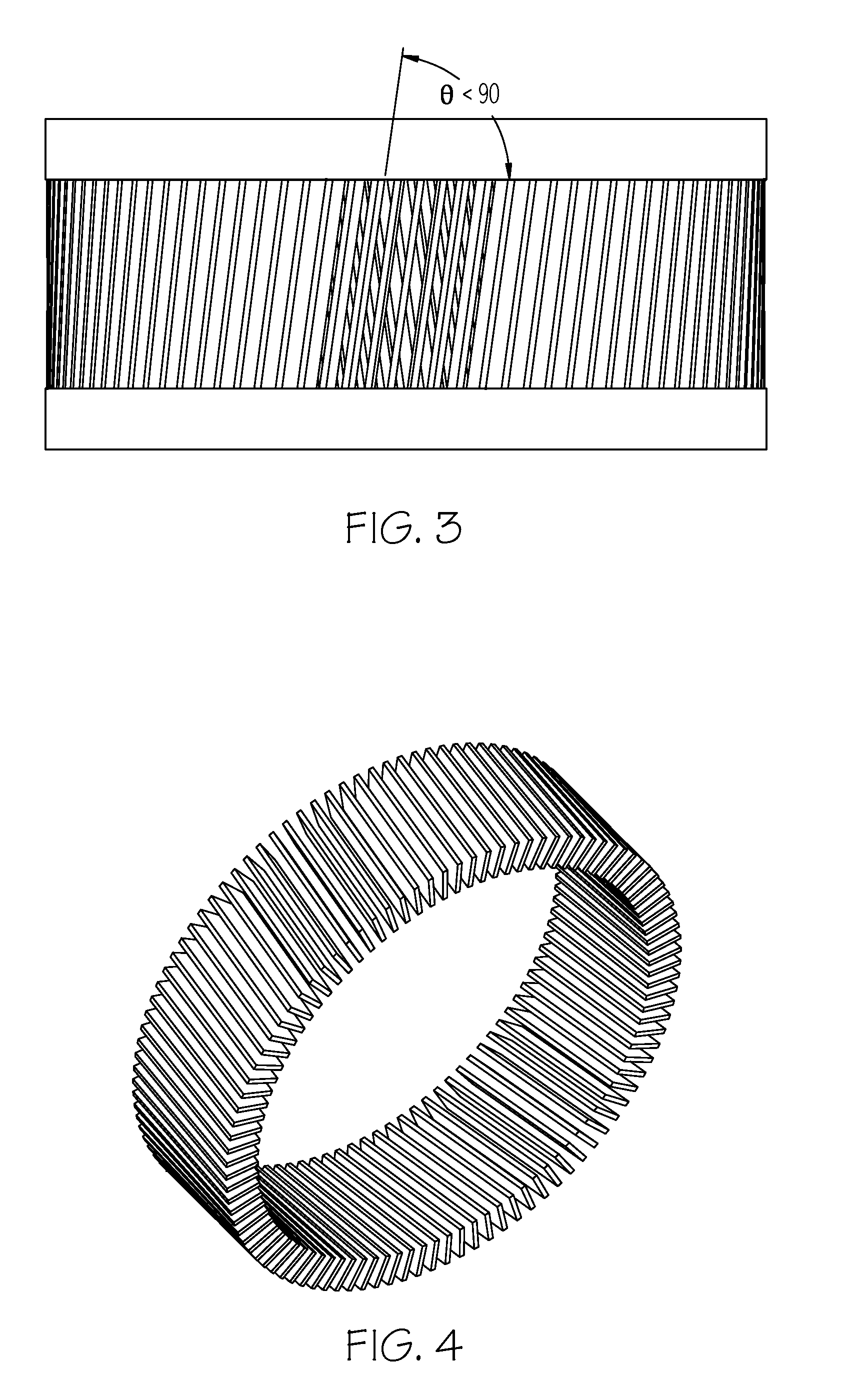
A squirrel cage rotor is a cylinder that is mounted on a shaft rotating in an induction motor. It contains longitudinal conductor bars set into squirrel slots and connected together at both ends by short rings forming a cage-like shape. FIG. 1 shows an illustration of one embodiment of a squirrel cage rotor. The core of the rotor is built with stacks of electrical steel laminations. FIG. 2 shows an illustration of one embodiment of a stack of laminate steel.

The field windings in the stator of an induction motor set up a rotating magnetic field around the rotor. The relative motion between this field and the rotation of the rotor induces electric current in the conductor bars. In turn these currents lengthwise in the conductors react with the magnetic field of the motor to produce force acting at a tangent to the rotor, resulting in torque to turn the shaft and the rotor. In effect, the rotor is carried around with the magnetic field, but at a slightly slower rate of rotation. The di...


PUM

PropertyMeasurementUnit
melting pointaaaaaaaaaa
porosityaaaaaaaaaa
thickaaaaaaaaaa

Abstract

Squirrel cage rotors of aluminum based material end rings joined with high conductive and durable material (such as copper) conductor bars for use in electric motors and methods of making them are described. The methods include forming conductor bars by casting or other metal forming methods in the slots of laminate steel stack, or positioning the preformed or premade solid conductor bars in the longitudinal slots of the stacked laminated steel, with bar ends extending out of the laminated steel stack ends, optionally coating the extended part of the conductors (bars) with a latent exoergic coating containing Al and one or more conductor bar chemical elements, positioning the laminated steel stack having conductors (bars) in a casting mold that forms the cavity of both end rings of the rotor, filling the end ring cavities with aluminum melt, and allowing the end rings to solidify under pressure. Alternatively, the conductor bars and end rings can be made separately and mechanically joined together.

Description

FIELD OF THE INVENTIONThe present invention relates to methods of manufacturing induction rotors for electrical machines and, more particularly, to methodologies and technologies to improve electrical conductivity and rotor durability by using different conductive materials and manufacturing processes between conductor bars and end rings, and to rotors having conductor bars made with high conductive materials.BACKGROUND OF THE INVENTIONIncreasing demands in fuel efficiency have made hybrid systems more attractive in the automotive industry. In addition to a conventional combustion engine, an electric motor is an important part of the hybrid system. To reduce the manufacturing cost of the hybrid system, many of the electric motors used in the hybrid systems are induction motors with cast aluminum or copper squirrel cage rotors. An operating characteristic of these induction motors, known as “slip,” is usually proportional to the electric resistance in the rotor, particularly in the c...

Claims


Application Information

Patent Timeline
Patent Type & Authority Applications(United States)
IPC IPC(8): H02K17/16H02K15/02
CPCH02K15/0012Y10T29/49009Y10T29/49012H02K17/18H02K17/165H02K17/20H02K17/168
Inventor WANG, QIGUIOSBORNE, MARK A.TUOHY, EUGENE C.
Owner GM GLOBAL TECH OPERATIONS LLC
Learn More