
Fast Microscale Actuators for Probe Microscopy

Active Publication Date: 2011-07-14
GEORGIA TECH RES CORP
View PDF29 Cites 50 Cited by
  • Summary
  • Abstract
  • Description
  • Claims
  • Application Information

AI Technical Summary

Benefits of technology

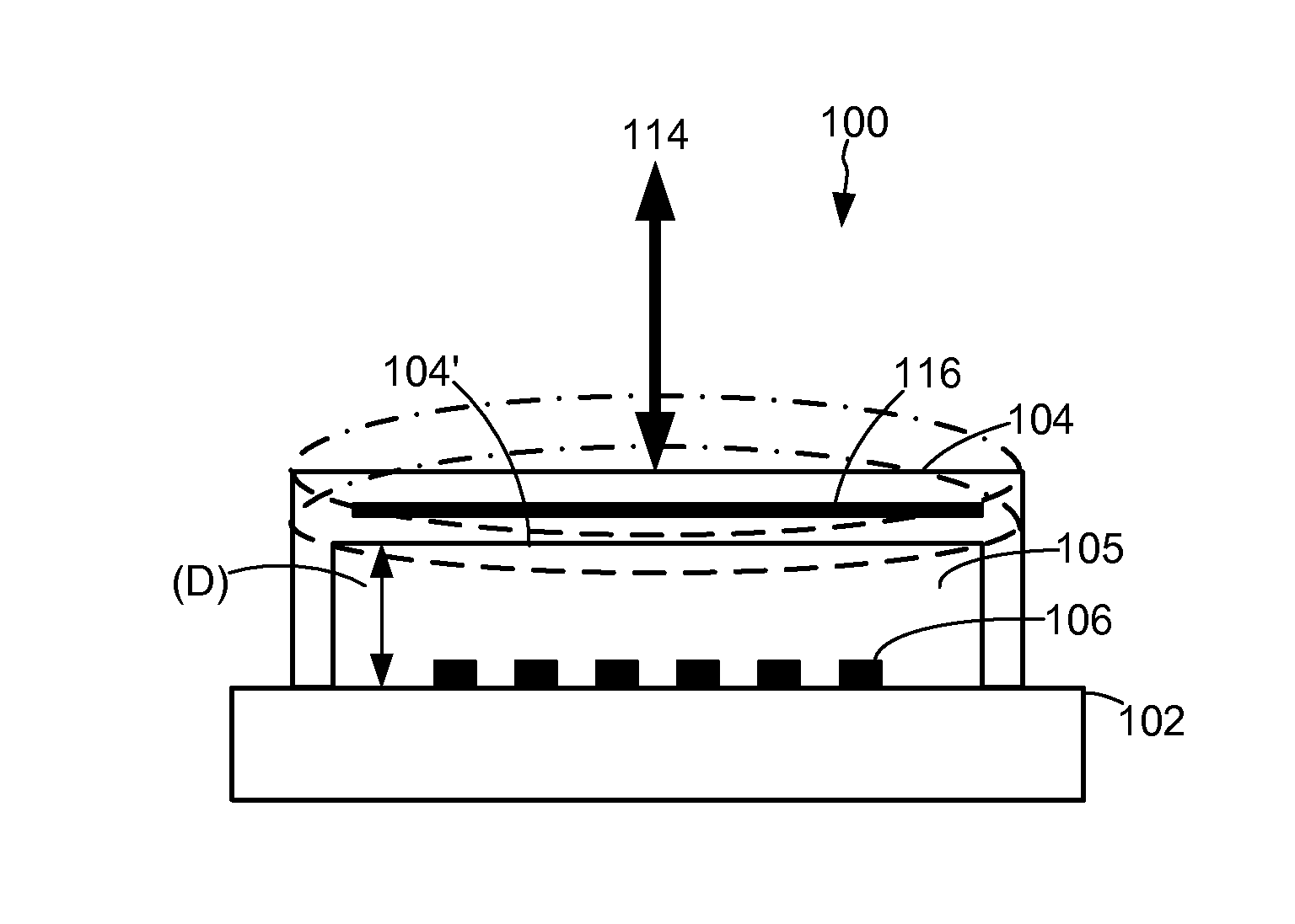
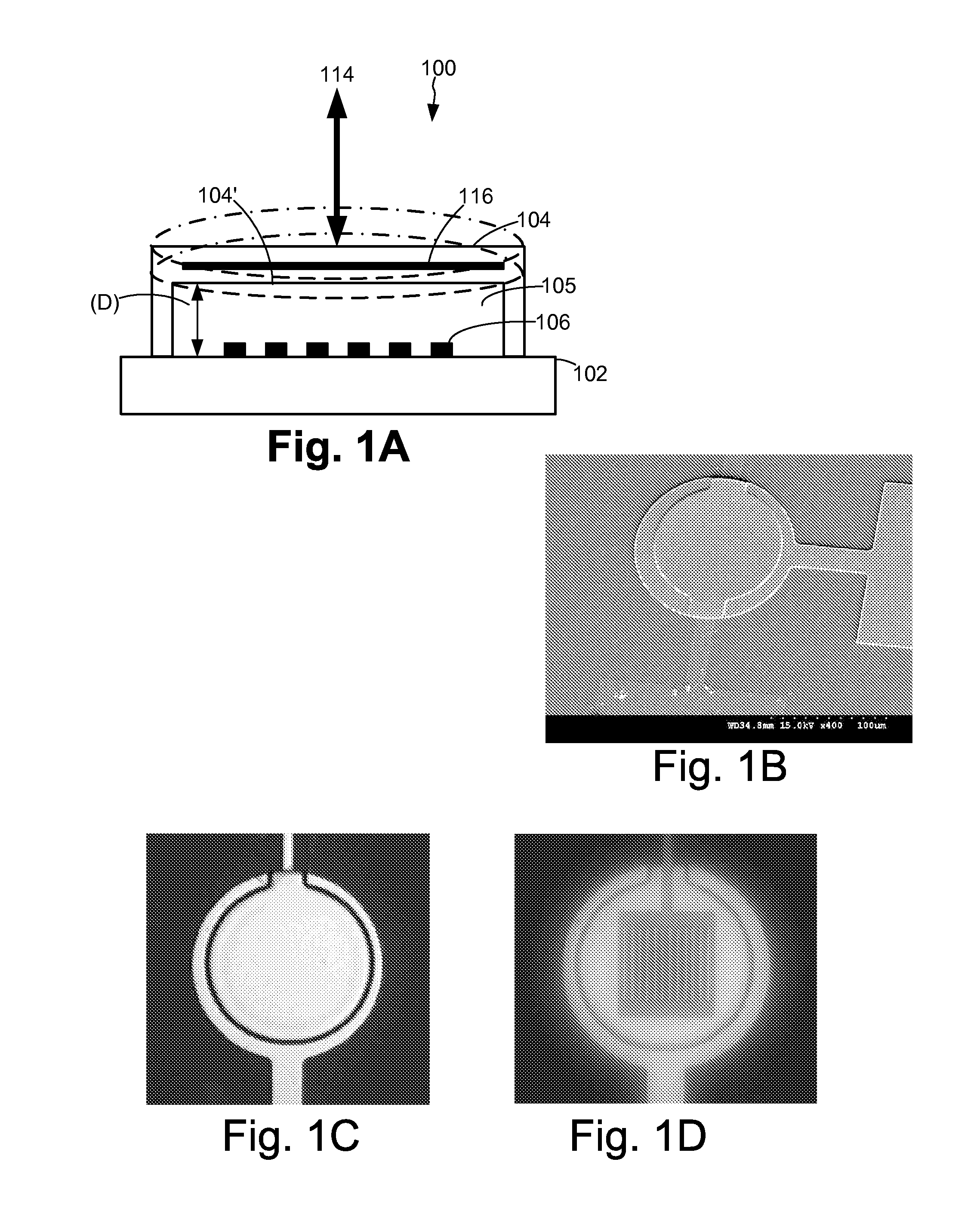
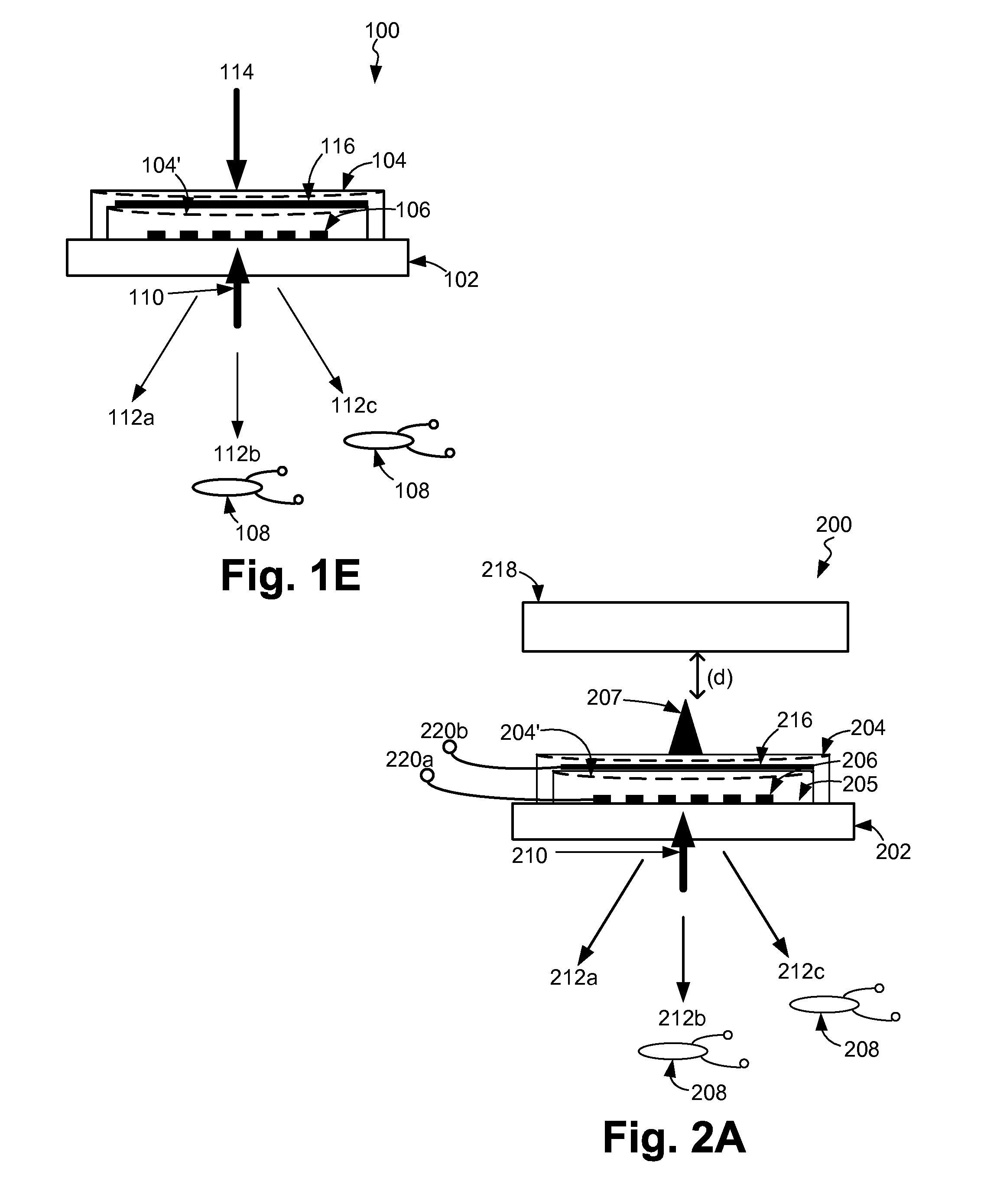
[0015]In another aspect, the invention is a parallel force spectroscopy apparatus that includes an array of sensing probes that are each capable of sensing a property of a sample. An array of actuation devices each includes a flexible surface that is spaced apart from a substrate. The array of

Problems solved by technology

Current cantilever-based structures for AFM probes and their respective actuation methodologies lack speed and sensitivity and have hindered progress in the aforementioned areas.
Imaging systems based on small cantilevers have been developed to increase the speed of AFMs, but this approach has not yet found wide use due to demanding constraints on optical detection and bulky actuators.
Several methods have been developed for quantitative elasticity measurements, but the trade-off between force resolution, measurement speed, and cantilever stiffness has been problematic especially for samples with high compliance and high adhesion.
Cantilever deflection signals measured during tapping mode imaging have been inverted to obtain elasticity information with smaller impact forces, but complicated dynamic response of the cantilever increases the noise level and prevents calculation of the interaction forces.
Arrays of AFM cantilevers with integrated piezoelectric actuators have been developed for parallel lithography, but low cantilever speed and complex fabrication methods have limited their use.
This can be quite limiting, as mechanical structures like cantilevers are resonant vibrating structures and they provide information mostly only around these resonances.
For example, in tapping mode imaging it is nearly impossible to recover all the information about the tip-sample interaction force, since the transient force applied at each tap cannot be observed as a clean time signal.
Moreover, conventional methods of imaging with scanning probes can be time consuming while others are often destructive because they require static tip-sample contact.
However, the only free variable in this mode, the phase, is related to the energy dissipation and it is difficult to interpret.
Further, the inverse problem of gathering the time-domain interaction forces from the tapping signal is not easily solvable due to complex dynamics of the AFM cantilever.
Studying biological samples in aqueous environments, which can be corrosive and electrically conducting, imposes challenging electrical isolation requirements.
These devices, which are used mainly for fast imaging so far, require complex fabrication processes and may be difficult to isolate electrically for operation in liquid environments.
Initial implementation of these force sensing integrated readout and active tip (FIRAT) devices used aluminum membranes over an unsealed air cavity and hence was not suitable for operation in immersion.

Method used


Image

  • Fast Microscale Actuators for Probe Microscopy
  • Fast Microscale Actuators for Probe Microscopy
  • Fast Microscale Actuators for Probe Microscopy

Examples


Embodiment Construction

[0090]A preferred embodiment of the invention is now described in detail. Referring to the drawings, like numbers indicate like parts throughout the views. As used in the description herein and throughout the claims, the following terms take the meanings explicitly associated herein, unless the context clearly dictates otherwise: the meaning of “a,”“an,” and “the” includes plural reference, the meaning of “in” includes “in” and “on.”

[0091]In the following description, reference is made to the accompanying drawings that form a part thereof, and in which is shown by way of illustration specific exemplary embodiments in which the invention may be practiced. These embodiments are described in sufficient detail to enable those skilled in the art to practice the invention and it is to be understood that other embodiments may be utilized and that changes may be made without departing from the scope of the invention. The following description is, therefore, not to be taken in a limited sens...


PUM


Abstract

A system for measuring a property of a sample includes an actuation device disposed on a substrate and includes a flexible surface spaced apart from the substrate and configured so as to allow placement of the sample thereupon. The actuation device also includes a vertical actuator that is configured to cause the flexible surface to achieve a predetermined displacement from the substrate when a corresponding potential is applied thereto. A sensing probe is disposed so as to be configured to interact with the sample thereby sensing the property of the sample.

Description

CROSS-REFERENCE TO RELATED APPLICATION(S)[0001]This application claims the benefit of U.S. Provisional Patent Application Ser. No. 60 / 830,445, filed Jul. 13, 2006, the entirety of which is hereby incorporated herein by reference. This application is also a continuation-in-part of, and claims the benefit of, U.S. patent application Ser. No. 11 / 260,238, filed Oct. 28, 2005, which is a non-provisional application claiming priority on U.S. Provisional Patent Application Ser. No. 60 / 691,972 filed on Jun. 17, 2005, and U.S. Provisional Patent Application Ser. No. 60 / 707,219 filed on Aug. 11, 2005, the entirety of each of which is hereby incorporated herein by reference.STATEMENT OF GOVERNMENT INTEREST[0002]This invention was made with support from the U.S. government under grant number ECS 0348582, awarded by National Science Foundation and grant number 1 R01 A1060799-01A2, awarder by the National Institutes of Health. The government may have certain rights in the invention.BACKGROUND OF ...

Claims


Application Information

Patent Timeline
IPC IPC(8): G01J3/45G01B11/14
CPCB82Y35/00G01N29/2406G01Q60/38G01N2291/0427G01Q10/045G01N29/2437
Inventor DEGERTEKIN, F. LEVENT
Owner GEORGIA TECH RES CORP
Learn More