
Developer container and image forming apparatus

a technology developer container, which is applied in the field of toner containers, can solve the problems of high production cost of image forming apparatus, and the likely development of contact defects between these conductive terminals

Active Publication Date: 2007-05-15
SHARP KK
View PDF27 Cites 37 Cited by
  • Summary
  • Abstract
  • Description
  • Claims
  • Application Information

AI Technical Summary

Benefits of technology

The invention provides a developer container for an image forming apparatus that can be detachably and attachably mounted. The container includes a cylindrical main body for containing developer, a supporting member for rotating the main body, and storage means for storing information about the developer. The container is connected to the image forming apparatus in a way that allows the information reading means to read the developer information even when the container rotates. The invention also includes an accommodation recess in the supporting member for fitting the storage means, and guide means for restricting displacement of the supporting member in a way that ensures reliable connection between the storage means and the information reading means. The invention provides an image forming apparatus with a detachable and attachable developer container, making it convenient for users to replace the container when needed.

Problems solved by technology

In the toner cartridge according to the third related art, however, the semiconductor memory member rotates with the toner cartridge and the construction of the image forming apparatus for connecting such a semiconductor member to the detection means is presumably complicated.
When the construction gets complicated like that, the production cost of the image forming apparatus becomes high.
Therefore, contact defect is likely to develop between these conductive terminals.
When such a contact defect occurs between the conductive terminals, communication cannot be conducted smoothly between the semiconductor memory member of the cartridge and the CPU of the apparatus main body.
Because the conductive terminal of the terminal is completely exposed, static electricity flows through the conductive terminal, for example, when a user touches it by hand and the information stored in the semiconductor memory member is likely to be destroyed.
The user is also likely to strongly grip the conductive terminal of the cartridge by mistake and to break it.

Method used


Image

  • Developer container and image forming apparatus
  • Developer container and image forming apparatus
  • Developer container and image forming apparatus

Examples


Embodiment Construction

[0067]Now referring to the drawings, preferred embodiments of the invention are described below.

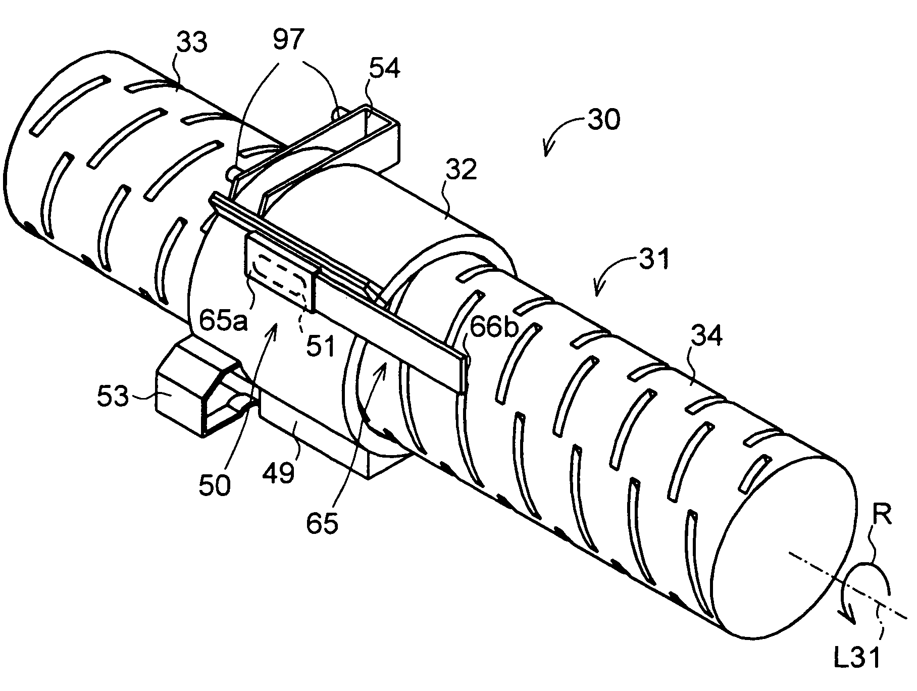
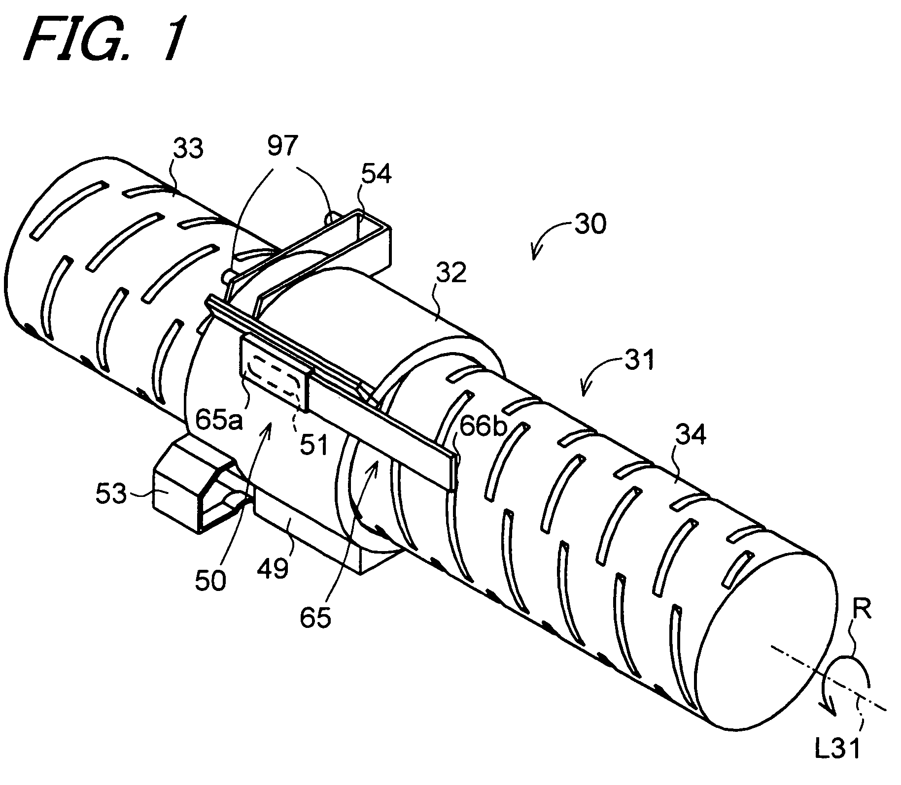
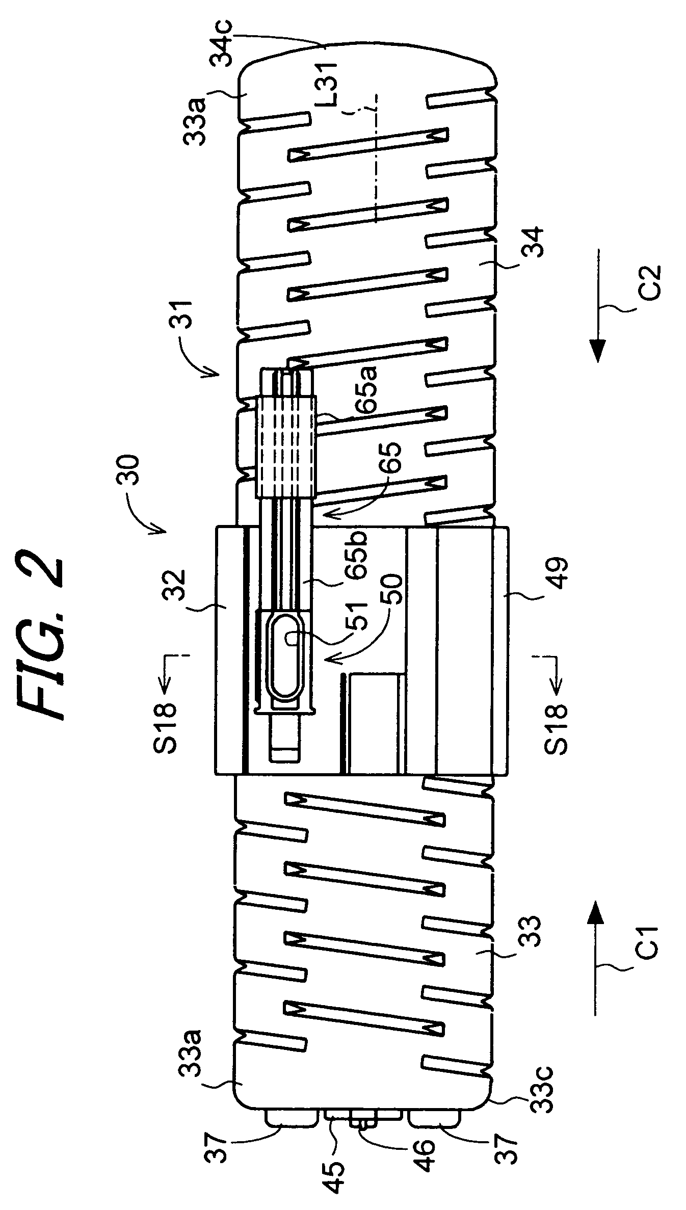
[0068]FIG. 1 is a perspective view showing a developer container 30 according to one embodiment of the invention. FIG. 2 is a front view showing the developer container 30. FIG. 3 is a left-hand side view showing the developer container 30. The developer container 30 includes a container main body 31 and a supporting member 32. The container main body 31, which has substantially a cylindrical shape, is designed to contain developer such as coloring toner for use in electrophotographic system-based image formation. The supporting member 32 supports the container main body 31 in such a way that the container main body 31 is rotatable about its axis L31. The developer container 30 is capable of containing, for example, 1400 grams of developer. Hereinafter, the axis L31 of the container main body 31 is also referred to as the “rotation axis L31”.

[0069]FIG. 4 is a front view showing the contai...


PUM


Abstract

A developer container includes a container main body, a supporting member and an information storage portion. The container main body is formed in a cylindrical shape and contains therein the developer for use in image formation. The supporting member supports the container main body rotatably about an axis. The information storage portion is fixed to the supporting member and stores developer associated information of the developer contained in the container main body. The information storage portion is connected to an information reading portion provided in an image forming apparatus in such a manner that the information reading portion can read out the developer associated information in the state where the developer container is mounted to the image forming apparatus.

Description

BACKGROUND OF THE INVENTION[0001]1. Field of the Invention[0002]The present invention relates to a toner container for containing toner for use in electrophotographic system-based image formation, and to an image forming apparatus in which the toner container is detachably and attachably mounted.[0003]2. Description of the Related Art[0004]When a plurality of photoconductive drums for transferring a toner image to a recording sheet is mounted in an image forming apparatus in such a fashion as to correspond to a duplication speed, a plurality of kinds of toners are used to correspond to the photoconductive drums. Therefore, containers having various capacities and various systems must be prepared as developer containers for containing the toners. In the case of a full-color image forming apparatus, for example, four kinds or four colors of toners are necessary and four developer containers for containing the each toner are mounted. It is therefore necessary to identify which develope...

Claims


Application Information

Patent Timeline
Patent Type & Authority Patents(United States)
IPC IPC(8): G03G15/00G03G15/08
CPCG03G15/0863G03G15/0855G03G15/0865G03G15/0872G03G2215/0697
Inventor HAYASHI, SHIGEKIDEGUCHI, MASANOBUKOYAMA, KAZUYANAGAHAMA, HITOSHI
Owner SHARP KK
Learn More