Feed side passage material and spiral separation membrane element

Inactive Publication Date: 2011-07-14
NITTO DENKO CORP
View PDF6 Cites 9 Cited by
  • Summary
  • Abstract
  • Description
  • Claims
  • Application Information

AI Technical Summary

Benefits of technology

Therefore, an object of the present invention is to provide a feed side passage material and a spiral separation membrane element using the feed side passage material that can effectively prevent biofouling because a sufficient antibacterial function is obtained even in the gap region between the constituting yarns.
In the case of using this composite semipermeable membrane, the separation membrane has an antibacterial layer containing a silver antibacterial agent and a polymer component, so that the microorganism contamination resistance property can be maintained for a long period of time by the antibacterial layer. In particular, by adjusting the weight ratio of the silver antibacterial agent and the polymer component in the antibacterial layer to be 55:45 to 95:5 (silver antibacterial agent:polymer component) and adding the silver antibacterial agent in an excessive amount as compared with the polymer component, it is possible to let a part of the silver antibacterial agent be exposed on the antibacterial layer surface, whereby an excellent microorganism contamination resistance property is exhibited. Also, since the antibacterial layer is formed directly or via another layer on the skin layer, and the antibacterial agent is not dispersed in the skin layer, the density of the skin layer is maintained. This can suppress the decrease in the performance of the skin layer, whereby not only the contamination resistance property but also the water permeation property and the salt inhibition ratio can be maintained to be high.

Problems solved by technology

However, it has been found out that none of the above antibacterial agents disclosed in the patent document 3, when used in a feed side passage material, produces a sufficient proliferation-suppressing effect to Escherichia coli.
Namely, since the feed side passage material is generally formed in a net shape, an antibacterial function is needed even in a gap region between the constituent yarns of the net; however, it has been found out that the above antibacterial agents do not produce an antibacterial effect in such a gap region.
In particular, when an organic antibacterial agent disclosed in the patent document 3 is used, the solubility is too high, making it difficult to extend the retaining time.
Also, an inorganic antibacterial agent such as a silver antibacterial agent has a low sustained-release property or a low diffusion function, so that the antibacterial area is narrow, thereby raising a problem in that the effect thereof is hardly extended to the space as a whole that is needed.

Method used


Image

  • Feed side passage material and spiral separation membrane element
  • Feed side passage material and spiral separation membrane element
  • Feed side passage material and spiral separation membrane element

Examples


example 1

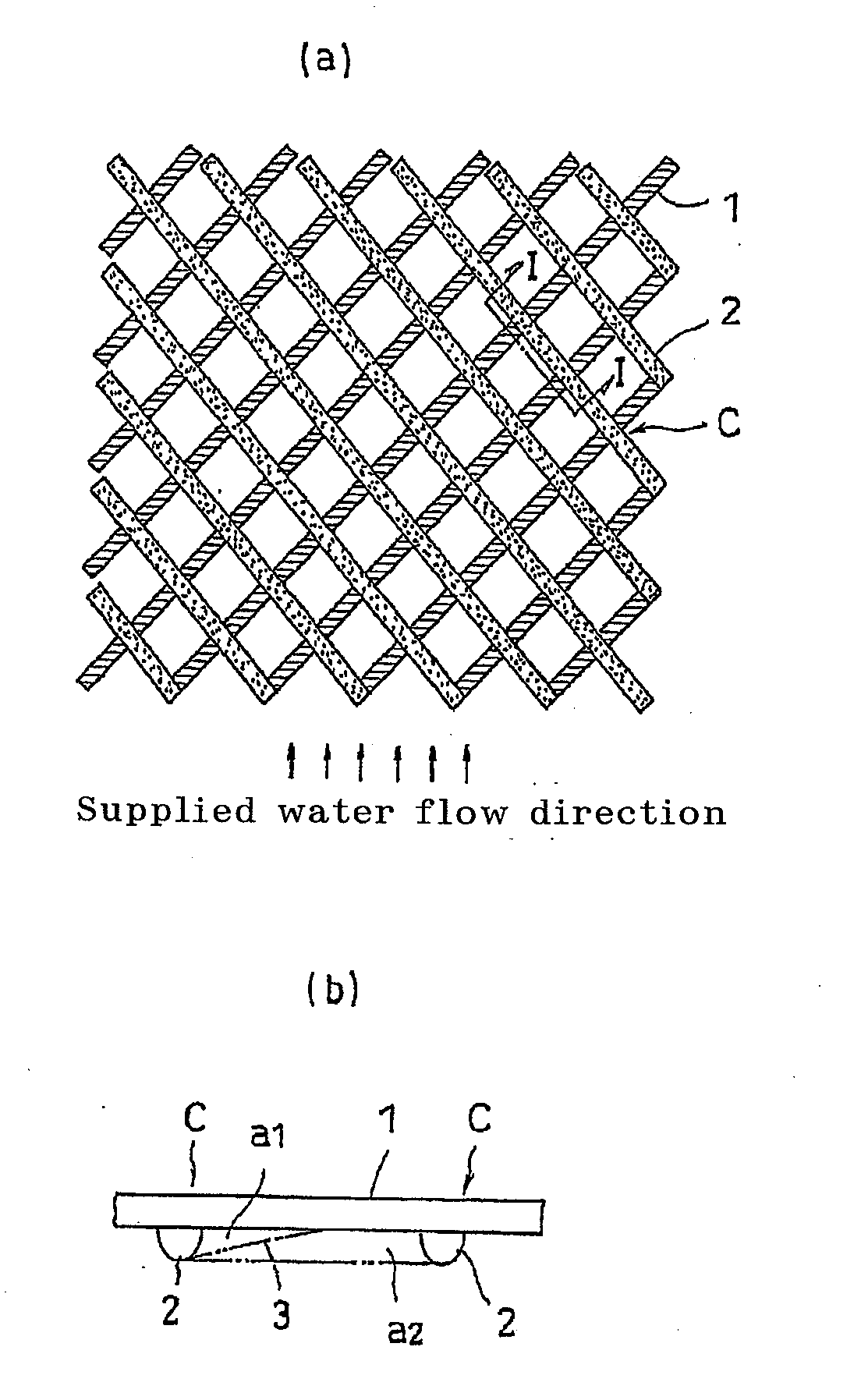
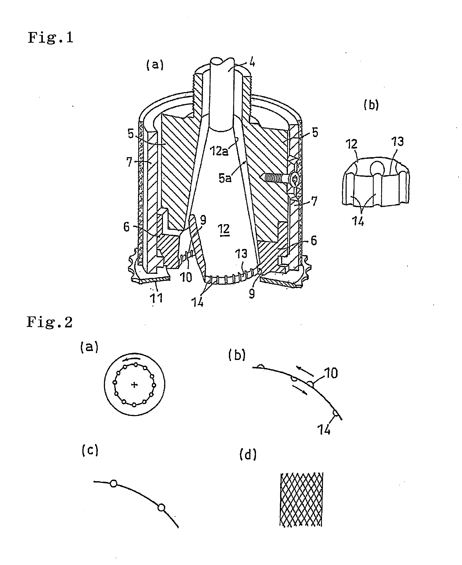
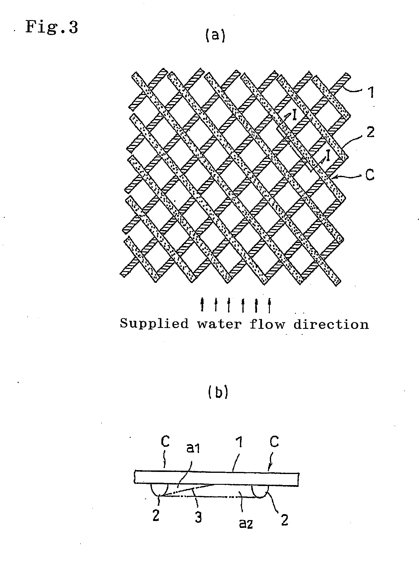
With use of an extruder equipped with a nozzle shown in FIG. 1, a pellet obtained by allowing 0.025 wt % of triclosan as an antibacterial agent in a polypropylene resin (F122G manufactured by Mitsui Chemical Co., Ltd.) is introduced, and is subjected to melt-extrusion at 260° C., whereby a feed side passage material having a net shape was formed by shear molding. During this time, the nozzle shape and the extrusion condition were adjusted so that the obtained net would have a total thickness of 0.79 mm, a constituent yarn diameter (width) of 0.3 mm, a yarn interval of 5 mm, and an intersection angle of 90°.

example 2

An aqueous solution containing 1.0 wt % of a silver antibacterial agent having an average particle size of 0.9 μm (Novalon AG1100 manufactured by Toa Synthesis Co., Ltd.) and 0.5 wt % of polyvinyl alcohol (saponification degree: 99%) was applied onto a skin layer of an ultra-low-pressure reverse osmosis composite membrane (type: ES20 manufactured by Nitto Denko Co., Ltd., skin layer: polyamide resin, performance: permeation flux 1.2 (m3 / m2·d) by the aforesaid measurement method, salt inhibition ratio of 99.6 (%)). Thereafter, the resultant was dried at 130° C. for 3 minutes in an oven to form an antibacterial layer, so as to fabricate a composite semipermeable membrane. A spiral separation membrane element shown in FIG. 7 was fabricated by using this composite semipermeable membrane, a feed side passage material obtained in Example 1, and a permeate side passage material (made of PET resin, thickness of 0.3 mm).

Before and after the water (having an SDI value of 3 to 6) obtained by a...

example 3

On a non-woven cloth base material, a solution obtained by dissolving 18 wt % of polysulfone (P-3500 manufactured by Solvay Co., Ltd.) into N,N-dimethylformamide (DMF) was uniformly applied to a Wet thickness of 200 μm, followed by immersion into a water bath at 40 to 50° C. for solidification and washing to fabricate a porous support. On this porous support, an aqueous solution of amine containing 3 wt % of m-phenylenediamine, 0.15 wt % of sodium laurylsulfate, 3 wt % of triethylamine, 6 wt % of camphorsulfonic acid, 5 wt % of isopropyl alcohol, and 0.5 wt % of silver nitrate was applied, and thereafter an extraneous aqueous solution of amine was removed to form an aqueous solution covered layer. Subsequently, on the surface of the aforesaid aqueous solution covered layer, an organic solution containing 0.2 wt % of trimesic acid chloride and naphthene hydrocarbon (Naphthesol 160 manufactured by Shin Nippon Petroleum Co., Ltd.) was applied. Thereafter, the resultant was held in a ho...


PUM

PropertyMeasurementUnit
Lengthaaaaaaaaaa
Weight ratioaaaaaaaaaa
Contentaaaaaaaaaa

Abstract

A feed side passage material is provided in which sufficient antibacterial activity is obtained even in the spaces among constituent yarns and which hence can effectively prevent biofouling. Also provided is a spiral separation-membrane element employing the feed side passage material. The feed side passage material, which is for use in a spiral separation-membrane element, is a feed side passage material in a net form constituted of yarns (1 and 2) containing a chlorophenol compound antibacterial. The spiral separation-membrane element comprises a perforated hollow core tube and, wound therearound, one or more separation membranes, one or more feed side passage materials, and one or more permeate side passage materials. The element is characterized in that the feed side passage materials each is said feed side passage material.

Description

TECHNICAL FIELDThe present invention relates to a feed side passage material for use in a spiral separation membrane element that separates a component existing in a liquid as well as to a spiral separation membrane element using the feed side passage material, and more particularly to a technique of imparting an antibacterial property to a spiral separation membrane element.BACKGROUND ARTConventionally, as a structure of a spiral separation membrane element, there is known one in which one or more separation membranes, one or more feed side passage materials, and one or more permeate side passage materials are wound around a perforated core tube (for example, see the patent document 1). In such a spiral separation membrane element, a feed side fluid (stock water) is guided to a separation membrane surface by the feed side passage material and, after being separated by being permeated through the separation membrane, a permeate side fluid (permeated water) is guided along the permea...

Claims


Application Information

Patent Timeline
IPC IPC(8): B01D63/00B01D63/10B01D71/00B01D65/02A01N31/16A01P3/00B01D65/08B01D69/12B01D71/56C02F1/50
CPCA01N31/16B01D63/10D01F1/103D01D5/18B01D65/08B01D2313/143B01D2321/10B01D2321/168B01D2323/42C02F1/44C02F1/441C02F1/444C02F1/505C02F2303/04C02F2303/20A01N25/10A01N25/34Y02A20/131B01D65/02B01D71/56B01D69/1213B01D69/1216B01D2325/48B01D63/101
Inventor UDA, YASUHIROKURATA, NAOKIYAMASHIRO, YUUJIMARUYAMA, KOUJIKONISHI, TAKAHISA
Owner NITTO DENKO CORP
Why Eureka
Try Eureka