Antenna coil, resonant antenna having antenna coil, and card type wireless device having resonant antenna

a technology of resonant antenna and antenna coil, which is applied in the direction of resonant antenna, substantially flat resonant elements, instruments, etc., can solve the problems of affecting the operation of the device. , to achieve the effect of high sensitivity

Inactive Publication Date: 2006-12-21
DENSO CORP
View PDF2 Cites 25 Cited by
  • Summary
  • Abstract
  • Description
  • Claims
  • Application Information

AI Technical Summary

Benefits of technology

[0009] In the above antenna coil, even of one of the unit coils is broken, another one of the unit coils functions as a backup coil so that sufficient antenna function is maintained. Further, since multiple unit coils are integrally accommodated in the coil case, the dimensions of the antenna coil are minimized. Further, the antenna coil is easily mounted on a substrate. Furthermore, combined direct current resistance of the coil body is reduced, compared with a conventional antenna. Thus, a Q value of the antenna coil is improved.
[0011] The inductance of the antenna coil and the capacitance of the resonant capacitor are determined such that a resonant point is set to be in a predetermined frequency range. However, if one of the unit coils is broken, the broken unit coil is coupled with the not-broken unit coils through the capacitance between the wirings of the unit coils so that a parasitic series resonant circuit is provided between a capacitance between wirings of the unit coils and the broken unit coil. When the resonant point of the parasitic series resonant circuit is disposed near the designed antenna resonant point, the sensitivity of the antenna may be reduced. Even in this case, in the above resonant antenna, the resonant point of the parasitic series resonant circuit is set to be sufficiently lower frequency side; and therefore, the antenna sensitivity of the resonant antenna is prevented from reducing.
[0013] The above wireless device is thin. Therefore, it is preferable to put the card type wireless device into a wallet or the like. Further, even when a coin in the wallet overlaps a principal surface of the card type wireless device, the antenna coil has sufficient area so that the coin does not interrupt the antenna coil completely. Thus, the card type wireless device has high sensitivity.

Problems solved by technology

Although the card type wireless device is a precision electric device, mechanical usage environment of the device is strict.
Accordingly, when the device receives mechanical impact or vibration, an antenna wiring may be broken, or a connection portion (in general, a solder portion) of a substrate terminal of the antenna may be broken or cause conduction error.
When the antenna in the card type wireless key of the vehicle is broken down, communication function of the wireless key is lost, and fundamental function such as a door-lock release function and / or an engine start function may be damaged.
However, in a case where the antenna is mutually used for the transmitting / receiving circuit and for the transponder, the transponder may be unavailable when the antenna is broken.

Method used


Image

  • Antenna coil, resonant antenna having antenna coil, and card type wireless device having resonant antenna
  • Antenna coil, resonant antenna having antenna coil, and card type wireless device having resonant antenna
  • Antenna coil, resonant antenna having antenna coil, and card type wireless device having resonant antenna

Examples


Embodiment Construction

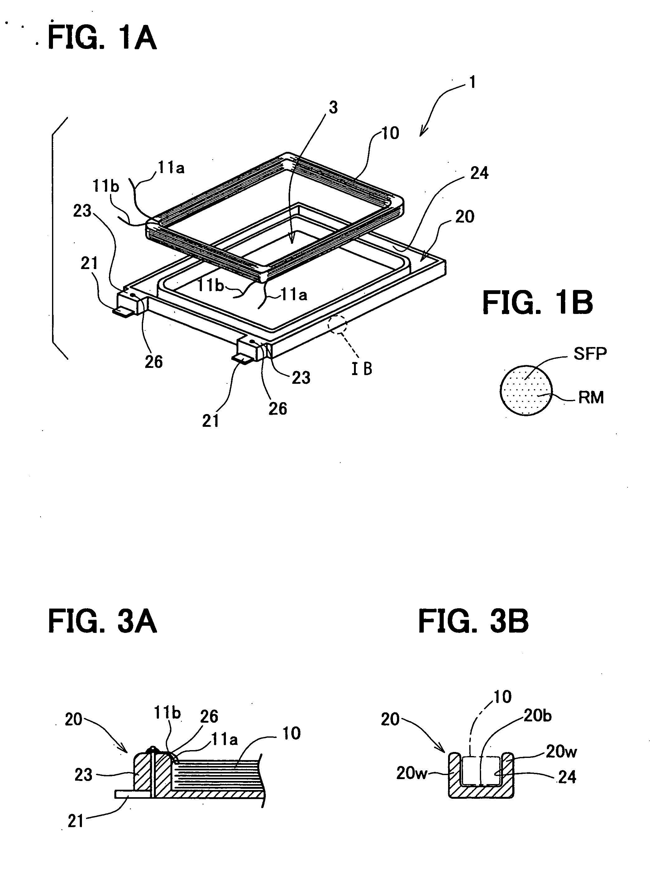
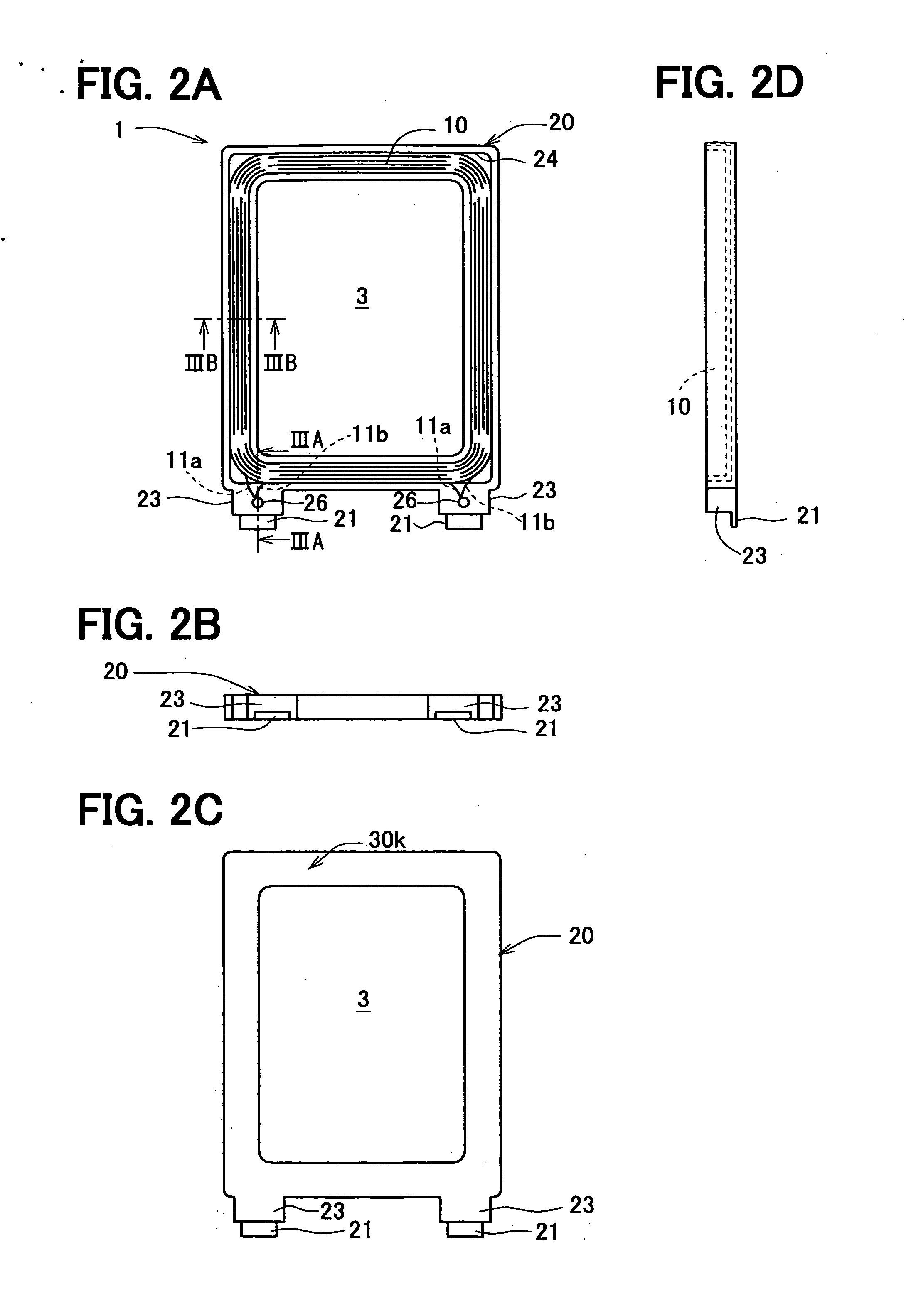
[0033]FIGS. 1A and 2B show an exploded perspective view of an antenna coil 1 as one example of the invention. FIGS. 2A to 2D are four face views (a plan view, a front view, a side view and a bottom view) of the antenna coil 1. The antenna coil 1 has a coil main body 10 of an air-core type of a flat shape, and a coil case 20. The coil case 20 is formed in a ring-shaped mode corresponding to the coil main body 10, and a coil storing portion 24 for storing this coil main body 10 is formed in the circumferential direction. As shown in FIG. 7, the coil main body 10 includes multiple unit coils 10a, 10b, which are connected in parallel. Each unit coil 10a, 10b has the same winding direction and the same number of turns. Although the coil main body 10 includes two unit coils 10a, 10b, the body 10 may have three or more unit coils.

[0034] The thickness of the coil main body 10 in its axial direction is set to be smaller than the radius of a circle of the same area as an area (planar outer s...


PUM


Abstract

An antenna coil includes: an air-core type flat coil body having a ring shape; and a coil case having a ring shape corresponding to the ring shape of the coil body. The coil case includes a coil accommodation space for accommodating the coil body. The coil accommodation space is disposed in a circumferential direction of the ring shape of the coil case. The coil body includes a plurality of unit coils, each of which has a same winding direction and a same number of turns. The unit coils are connected in parallel each other.

Description

CROSS REFERENCE TO RELATED APPLICATION [0001] This application is based on Japanese Patent Application No. 2005-179154 filed on Jun. 20, 2005, the disclosure of which is incorporated herein by reference. FIELD OF THE INVENTION [0002] The present invention relates to an antenna coil, a resonant antenna having the antenna coil, and a card type wireless device having the resonant antenna. BACKGROUND OF THE INVENTION [0003] In recent years, an electronic key system (also called a smart entry system, etc.) is spread. In this electronic key system, ID authentication is performed by wireless communication between this system and a wireless electronic key (also called a portable device) carried by a user. Further, controls of locking / unlocking of a door lock, engine starting, etc. of an automotive vehicle can be performed by commands from this portable device. In the above wireless electronic key, a demand for constructing this wireless electronic key as the card type wireless device made t...

Claims


Application Information

Patent Timeline
IPC IPC(8): G06K7/08G06K19/06
CPCH01Q7/00H01Q1/2225H01Q7/04H01Q9/0407G06K19/07749H04B5/26
Inventor NAITO, HIROMICHI
Owner DENSO CORP
Why Eureka
Try Eureka